Methods of Voltage Control in Transmission Lines:
Practically each equipment used in power system are rated for a certain voltage with a permissible band of voltage variations. Voltage at various buses must, therefore, be controlled within a specified regulation figure. This article will discuss the Methods of Voltage Control in Transmission Lines by means of which voltage at a bus can be controlled.
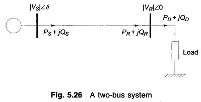
Consider the two-bus system shown in Fig. 5.26. For the sake of simplicity let the line be characterized by a series reactance (i.e. it has negligible resistance). Further, since the torque angle δ is small under practical conditions, real and reactive powers delivered by the line for fixed sending-end voltage |VS| and a specified receiving-end voltage |VSR| can be written as below from Eqs. (5.71) and (5.73).
Equation (5.83) upon quadratic solution can also be written as

Since the real power demanded by the load must be delivered by the line,
![]()
Varying real power demand PD is met by consequent changes in the torque angle δ.
It is, however, to be noted that the received reactive power of the line must remain fixed at QSR as given by Eq. (5.83) for fixed |VS| and specified |VSR|. The line would, therefore, operate with specified receiving-end voltage for only one value of QD given by
![]()
Practical loads are generally lagging in nature and are such that the VAR demand QD may exceed QSR. It easily follows from Eq. (5.83) that for QD > QSR the receiving-end voltage must change from the specified value |VSR| to some value |VR| to meet the demanded VARs. Thus
![]()
The modified |VR| is then given by
![]()
Comparison of Eqs. (5.84) and (5.85) reveals that for QD = QR = QSR, the receiving-end voltage is |VSR|, but for QD = QR > QSR,
![]()
Thus a VAR demand larger than QSR is met by a consequent fall in receiving-end voltage from the specified value. Similarly, if the VAR demand is less than QSR , it follows that
![]()
Indeed, under light load conditions, the charging capacitance of the line may cause the VAR demand to become negative resulting in the receiving-end voltage exceeding the sending-end voltage.
In order to regulate the line voltage under varying demands of VARs, the two methods discussed below are employed.
Reactive Power Injection:
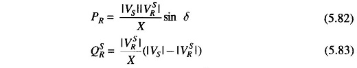
It follows from the above discussion that in order to keep the receiving-end voltage at a specified value |VSR|, a fixed amount of VARs (QSR) must be drawn from the line. To accomplish this under conditions of a varying VAR demand QD, a local VAR generator (controlled reactive power source/compensating equipment) must be used as shown in Fig. 5.27.
The VAR balance equation at the receiving-end is now
![]()
Fluctuations in QD are absorbed by the local VAR generator QC such that the VARs drawn from the line remain fixed at QSR The receiving-end voltage would thus remain fixed at |VSR| (this of course assumes a fixed sending-end voltage |VS|. Local VAR compensation can, in fact, be made automatic by using the signal from the VAR meter installed at the receiving-end of the line.
Two types of VAR generators are employed in practice—static type and rotating type. These are discussed below.
Static VAR generator:
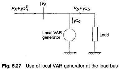
It is nothing but a bank of three-phase static capacitors and/or inductors. With reference to Fig. 5.28, if |VR| is in line kV, and XC is the per phase capacitive reactance of the capacitor bank on an equivalent star basis, the expression for the VARs fed into the line can be derived as under.
![]()
If inductors are employed instead, VARs fed into the line are
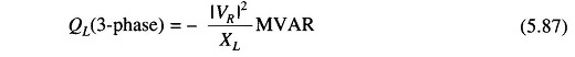
Under heavy load conditions, when positive VARs are needed, capacitor banks are employed; while under light load conditions, when negative VARs are needed, inductor banks are switched on.
The following observations can be made for static VAR generators.
- Capacitor and inductor banks can be switched on in steps. However, stepless (smooth) VAR Methods of Voltage Control in Transmission Lines can now be achieved using SCR (Silicon Controlled Rectifier) circuitry.
- Since QC is proportional to the square of terminal voltage, for a given capacitor bank, their effectiveness tends to decrease as the voltage sags under full load conditions.
- If the system voltage contains appreciable harmonics, the fifth being the most troublesome, the capacitors may be overloaded considerably.
- Capacitors act as short circuit when switched on.
- There is a possibility of series resonance with the line inductance particularly at harmonic frequencies.
Rotating VAR generator:
It is nothing but a synchronous motor running at no-load and having excitation adjustable over a wide range. It feeds positive VARs into the line under overexcited conditions and feeds negative VARs when underexcited. A machine thus running is called a synchronous condenser.
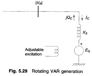
Figure 5.29 shows a synchronous motor connected to the receiving-end bus bars and running at no load. Since the motor draws negligible real power from the bus bars, EG and VR are nearly in phase. XS is the synchronous reactance of the motor which is assumed to have negligible resistance. If |EG| and |VR| are in line kV, we have
![]()
It immediately follows from the above relationship that the machine feeds positive VARs into the line when |EG| > |VR| (overexcited case) and injects negative VARs if |EG| < |VR| (underexcited case). VARs are easily and continuously adjustable by adjusting machine excitation which controls |EG|.
In contrast to static VAR generators, the following observations are made in respect of rotating VAR generators.
- These can provide both positive and negative VARs which are continuously adjustable.
- VAR injection at a given excitation is less sensitive to changes in bus voltage. As |VR| decreases and (|EG| — |VR|) increases with consequent smaller reduction in QC compared to the case of static capacitors.
From the observations made above in respect of static and rotating VAR generators, it seems that rotating VAR generators would be preferred. However, economic considerations, installation and maintenance problems limit their practical use to such buses in the system where a large amount of VAR injection is needed.
Control by Transformers:
The VAR injection method discussed above lacks the flexibility and economy of voltage control by transformer tap changing. The transformer tap changing is obviously limited to a narrow range of Methods of Voltage Control in Transmission Lines. If the voltage correction needed exceeds this range, tap changing is used in conjunction with the VAR injection method.
Receiving-end voltage which tends to sag owing to VARs demanded by the load, can be raised by simultaneously changing the taps of sending-and receiving-end transformers. Such tap changes must be made ‘on-load’ and can be done either manually or automatically, the transformer being called a Tap Changing Under Load (TCUL) transformer.
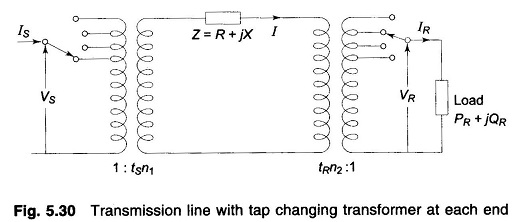
Consider the operation of a Methods of Voltage Control in Transmission Lines with a tap changing transformer at each end as shown in Fig. 5.30. Let tS and tR be the fractions of the nominal transformation ratios, i.e. the tap ratio/nominal ratio. For example, a trans-former with nominal ratio 3.3 kV/11 kV when tapped to give 12 kV with 3.3 kV input has is tS = 12/11 = 1.09.
With reference to Fig. 5.30 let the impedances of the transformer be lumped in Z along with the line impedance. To compensate for voltage in the line and transformers, let the transformer taps be set at off nominal values, tS and tR. With reference to the circuit shown, we have
![]()
From Eq. (5.75) the voltage drop referred to the high voltage side is given by
![]()
Now
![]()
In order that the voltage on the HV side of the two transformers be of the same order and the tap setting of each transformer be the minimum, we choose
![]()
Substituting tR = 1/tS in Eq. (5.91) and reorganizing, we obtain
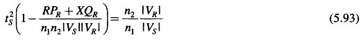
For complete voltage drop compensation, the right hand side of Eq. (5.93) should be unity.
It is obvious from Fig. 5.30 that tS > 1 and tR < 1 for voltage drop compensation. Equation (5.90) indicates that tR tends to increase the voltage |ΔV| which is to be compensated. Thus merely tap setting as a method of voltage drop compensation would give rise to excessively large tap setting if compensation exceeds certain limits. Thus, if the tap setting dictated by Eq. (5.93), to achieve a desired receiving-end voltage exceeds the normal tap setting range (usually not more than ± 20%), it would be necessary to simultaneously inject VARs at the receiving-end in order to maintain the desired voltage level.