Small Signal Amplifiers Articles:
Single Stage Common Emitter Amplifier Circuit: Specification – Bias circuit design for the Single Stage Common Emitter Amplifier Circuit in shown in Fig. 12-1 and ac analysis of the circuit is already explained. Design of this circuit (or any other circuit) … (Read More)
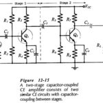
Capacitor Coupled Two Stage CE Amplifier: A Capacitor Coupled Two Stage CE Amplifier circuit is shown in Fig. 12- 15 . Stage-1 is capacitor-coupled (via C3) to the input of Stage-2. The signal is applied to the input of Stage-1, and the … (Read More)
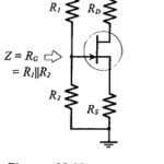
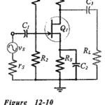 Single Stage Common Source Amplifier: Bias circuit design for the Single Stage Common Source Amplifier in shown in Fig. 12-10. As with the common-emitter BJT circuit, design commences with specification of the supply voltage, amplification, frequency response, load impedance, etc. Selection of … (Read More)
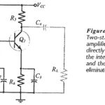
Direct Coupled Circuits: For economy, the number of components used in any circuit should be kept to a minimum. The use of direct coupling between stages is one way of eliminating components. Figure 12-20 shows a Direct Coupled Circuits that has the … (Read More)
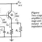
Two Stage Direct Coupled Common Emitter Amplifier: Figure 12-23 shows Two Stage Direct Coupled Common Emitter Amplifier. This time the second stage is a common collector circuit, or emitter follower. Stage 2 gives the circuit a very low output impedance, but … (Read More)
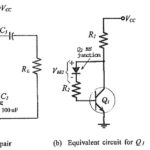
DC Feedback Pair with Two Amplification Stages: The DC Feedback Pair with Two Amplification Stages circuit shown in Fig. 12-25(a). The base of transistor Q2 is directly connected to the collector of Q1, and the base of Q1 is biased from … (Read More)
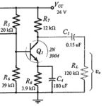
BIFET Amplifier: BJT-FET Considerations: Two-stage BJT circuits usually have relatively low input impedances. To increase Zi, a field effect transistor may be used as the first stage. Circuits which are composed of BJTs and FETs are termed BIFET Amplifier circuits. … (Read More)
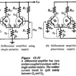
Differential Amplifier Circuit using Transistors: The Differential Amplifier Circuit using Transistors is widely applied in integrated circuitry, because it has both good bias stability and good voltage gain without the use of large bypass capacitors. Differential amplifiers can also be constructed … (Read More)
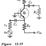
Capacitor Coupled Common Base Amplifier: A practical Capacitor Coupled Common Base Amplifier (using a plus/minus supply) is shown in Fig. 12-39. The CB circuit is analysed already, where it is found to … (Read More)
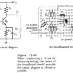
Amplifier Testing: Preparation – Transistor Amplifier Testing and other circuits should be tested in a methodical fashion; otherwise the results obtained may be useless. The circuit should first be carefully constructed in bread-board form, placing the components to resemble the circuit … (Read More)