BIFET Amplifier:
BJT-FET Considerations : Two-stage BJT circuits usually have relatively low input impedances. To increase Zi, a field effect transistor may be used as the first stage. Circuits which are composed of BJTs and FETs are termed BIFET Amplifier circuits. Since a FET circuit normally has much lower voltage gain than a BJT circuit, a BIFET Amplifier circuit can be expected to have lower overall voltage gain than a two-stage BJT circuit.
Two-stage FET circuits can be designed and constructed. However, the voltage gain of a two-stage FET circuit is substantially lower than that of a BIFET circuit, and there are no advantages to offset the lower voltage gain
Capacitor-Coupled BIFET Amplifier:
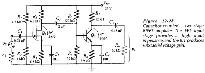
A two-stage, capacitor-coupled BIFET Amplifier circuit is shown in Fig. 12-28. The input stage provides a very high input resistance and a voltage gain usually ranging from 5 to 15. Stage 2 has the typical bipolar voltage gain of 200 to 500, depending upon transistor parameters and resistor values. Each stage is designed Independently. The two stages of the circuit shown in Fig. 12-28. In this case, C3 is omitted and C3 in Fig. 12-28 is the interstage coupling capacitor.
Direct-Coupled BIFET Amplifier:
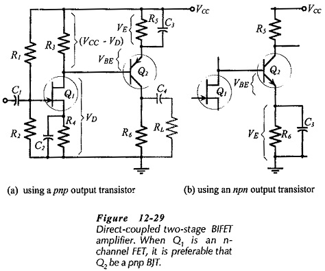
In the direct-coupled BIFET Amplifier circuit in Fig. 12-29(a), transistor Q1 is an n-channel JFET and Q2 is a pnp bipolar transistor. An npn BJT could be used in the circuit, as illustrated in Fig. 12-29(b); however, this arrangement uses a large voltage drop across Q2 emitter resistor (R6), leaving a smaller voltage drop across the collector resistor (R5). Q2 can also be driven into saturation if the drain current of Q1 is lower than the design level. For the circuit in Fig. 12-29(a), VCE2 is increased when ID1 is less than the ID(max) design level