Single Phase Induction Motor:
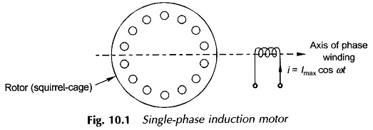
A Single Phase Induction Motor comprises a single-phase distributed winding on the stator and normal squirrel-cage rotor as shown schematically in Fig. 10.1 wherein for convenience the stator winding is shown in concentrated form.
There are two important methods of analyzing this motor, namely
- Cross-field theory and
- Rotating field theory.
As the latter is more akin to the 3-phase induction machine theory advanced earlier, it will be adopted here.
Pulsating Field as Two Rotating Fields:
Figure 10.1 gives the schematic diagram of a Single Phase Induction Motor with one stator winding and a squirrel-cage rotor. The winding is distributed in space so that the space fundamental of mmf is the most dominant component of the actual mmf distribution. The space harmonics of mmf, as in the case of a 3-phase induction motor, would then be ignored. When the winding carries a sinusoidal current, it produces a sinusoidally space-distributed mmf whose peak value pulsates with time. As seen from the axis of the winding, the mmf at any angle θ is
![]()
where θ is the angle measured from the winding axis. Now
![]()
so that the mmf has both space and time distribution expressed as
![]()
This equation can be trigonometrically manipulated into the form
![]()
Equation (10.4) tells us that a pulsating single-phase field can be considered as superposition of two rotating fields rotating at synchronous speed (ω=2πf elect. rad/s) in opposite directions:
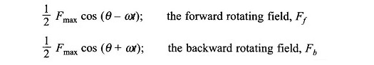
Both these fields have an amplitude equal to (1/2)Fmax where Fmax is the maximum value of the pulsating mmf along the axis of the winding. The splitting of a single pulsating field into two rotating fields rotating in opposite directions is illustrated in Fig. 10.2. This figure shows the location of the rotating fields at the time instant when the mmf along the winding axis is +Fmax.
Rotor Slip with respect to Two Rotating Fields:
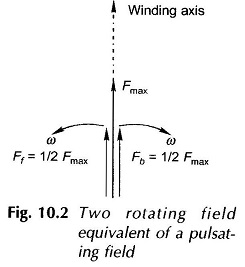
For the single-winding case illustrated in Fig. 10.1, Fig. 10.3 shows the forward and backward rotating fields along with the rotor which is rotating at speed n in the direction of the forward field. The slip of the rotor with respect to the forward rotating field Ff is then
![]()
while the rotor slip with respect to the backward rotating field Fb is
Thus the rotor slips with respect to the two rotating fields are different and are given by Eqs (10.5a) and (10.5b).
Torque-Speed Characteristic of Single Phase Induction Motor:
Qualitative Treatment Under stationary rotor condition (n = 0, i.e. s = 1), the two rotating fields slip past the rotor at the same slip, s = 1, (see Eqs (10.5a) and (10.5b)) inducing equal currents in the squirrel-cage rotor. The two rotating fields have the same strength and produce equal and opposite torques resulting in net starting torque of zero value. The single-winding Single Phase Induction Motor is thus nonself-starting. Further, the two rotating fields induce a resultant emf in the stator which balances the applied voltage assuming low leakage impedance of the stator winding.
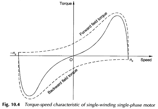
If, however, the rotor is made to run at speed n in the direction of the forward field, the two slips are now s and (2 – s). For normal operation (2 – s) ≫ s and as a consequence the backward field induced rotor currents are much larger than at standstill and have a lower power factor. The corresponding opposing rotor mmf, in presence of the stator impedance, causes the backward field to be greatly reduced in strength. On the other hand, the low-slip forward rotating field induces smaller currents of a higher power factor in the rotor than at standstill. This leads to great enhancement in the forward flux wave. This reduction in the backward field and strengthening of the forward field is slip-dependent and the difference increases as slip s (with respect to the forward field) reduces or the rotor speed in the forward direction becomes close to the synchronous speed. Infact, at near about the synchronous speed, the forward field may be several times the backward field. As a result there is a net running torque. The two fields together must always induce the stator winding emf to balance the applied voltage. The complete torque-speed characteristic as the sum of the two (forward and backward) torque-speed characteristics is drawn in Fig. 10.4. The result of weakening of one field and simultaneous strengthening of the other leads to a torque-speed characteristic like that of a 3-phase induction motor in the speed region close to synchronous. The fact of zero starting torque is immediately observed here.
The forward field and the rotor’s backward reaction field and also the backward field and the rotor’s forward reaction field move in opposite directions with relative speeds of 2ns producing second harmonic pulsating torques with zero average value. As a consequence a Single Phase Induction Motor is a noisier motor than a 3-phase one which has no such pulsating torque. The pulsating torque in fact is a direct consequence of the pulsating power in a single-phase circuit. In fact in the torque-speed characteristic of a Single Phase Induction Motor, the torque ordinate represents the average torque.
Semi–quantitative Analysis:
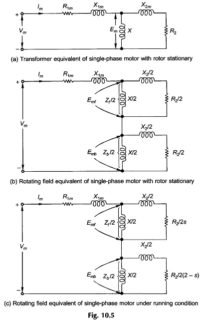
To develop the circuit model of a single-winding, single-phase motor on semi-quantitative basis, heuristic arguments will be used. The motor with a stationary rotor merely acts like a transformer with a circuit model as shown in Fig. 10.5(a), the core-loss branch having been ignored. The suffix m in the stator refers to the main winding and Em is the stator-induced emf set up by the alternating field.
The motor is now viewed from the point of view of the rotating field theory. The resultant induced emf is composed of two equal components induced by the two oppositely rotating fields of the same strength, i.e.
![]()
The magnetizing and rotor impedances are divided into two equal halves connected in series as shown in Fig. 10.5(b); the motor behaves like two series connected motors one corresponding to each rotating field. The circuits of the two component motors are identical under stationary condition as the rotor has the same slip with respect to each rotating field.
When the rotor is running at speed n with respect to the forward field, the slip is s with respect to it and (2 – s) with respect to the backward rotating field so that the circuit model now modifies as in Fig. 10.5(c).
It is easily seen from this figure that Zf/2 ≫ Zb/2 and so Emf ≫ Emb, i.e., the forward field motor effect predominates, creating a running torque.
Practical necessity dictates that the two rotating fields are made to have unequal strength under stationary conditions thereby making the motor self-starting. This requires one more winding on the motor called auxiliary winding which is in space quadrature with the main winding and comprises smaller number of turns of thinner wire. This winding may be cut out of circuit once the motor has started except in case of the capacitor-run motor where it may be left connected serving the purpose of improving the overall power factor.
Performance Analysis:
The performance of a Single Phase Induction Motor can be obtained by analysis of the circuit model of the motor given in Fig. 10.5(c), as was done for the case of a 3-phase induction motor. The results are similar to those for a 3-phase induction motor because the circuit model is essentially the same.
The air-gap powers for the forward and backward fields are given by
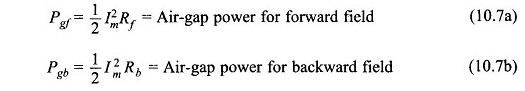
where Im is the main winding current and Rf and Rb are the real parts of the complex number impedances Z̅f and Z̅b respectively in Fig. 10.5(c).
The torques produced by the two fields can be expressed as
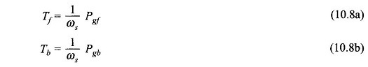
where ωs = synchronous speed in rad/s.
Since the two fields are rotating in opposite directions the torque produced by the two oppose each other. The resultant torque developed is therefore

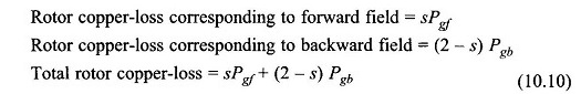
The rotor copper losses are in general equal to slip times the air-gap power. Thus
The electrical power converted to gross mechanical form is
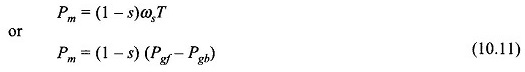
Equation (10.11) can also be written as
![]()
This implies that the electrical power input to the motor neglecting the stator copper-loss is
![]()