Pilot Wire Protection Relay:
In this case the auxiliary Pilot Wire Protection Relay are provided to carry the information signals from one end to the other. Protective systems requiring the use of pilot wires on transmission lines operate on the principle of differential protection. There are basically two forms of differential protection schemes used for transmission line protection: (i) longitudinal; (ii) transverse.
The longitudinal differential protection operating principle is based on the comparison of the magnitude and phase of the currents at the two ends of the protected section.
Some of the commonly used longitudinal differential schemes are described below.
(a) The Translay Scheme (AEI): The scheme is shown in Fig. (5.38). It is of the balanced voltage type and is suitable for pilot circuits up to a loop resistance of 800 ohms. Associated with the CTs at each end is an induction disc type relay whose secondary circuits are connected in opposition by Pilot Wire Protection Relay. Summation of the secondary line current is carried out in the tapped winding of the upper electromagnet of the relay. The upper electromagnet system acts as a quadrature transformer and produces at the pilot terminals a voltage which varies with the primary current. No current will flow in the circuit under normal conditions; whereas in the case of a fault there is a discrepancy between the currents flowing at the two ends which will cause a resultant difference between the secondary voltages and thus a current in this circuit. Under such conditions when the current flow occurs in both the upper and the lower magnet the relay operates.
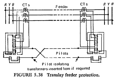
Compensation for pilot capacitance currents is made by providing a copper loop fitted to the centre limb of the upper electromagnet. The flux from this magnet leads the pilot voltage (or the secondary voltage) and produces a flux in the lower magnet in phase with the upper coil flux thus producing no torque in the disc. Because it is necessary for local current to be present for the production of torque, the protection will operate at the fault feeding end only on an internal fault.
The overall performance of the scheme is as follows:
Minimum earth-fault settings 22-40%
Minimum phase-fault settings 45-90%
Minimum three-phase fault setting 52%
Operating time at 5 times the fault setting 0.12s
It is also possible to provide bias feature by providing a second copper loop fitted on an outer limb of the upper magnet. With such an arrangement when the current flows only in the upper coil the relay behaves as a shaded pole type, but the torque produced is arranged to act in the reverse sense (restraint). This permits to some extent the use of unmatched CTs at the two ends.
(b) Solkor Scheme (Reyrolle): The Scheme and the characteristics of the relay are shown in Fig. (5.39).
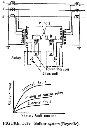
This is also essentially a balanced voltage feeder protection scheme. Separate saturable summation transformers are provided which are designed to saturate at about 1.5 times the CT secondary rating for an earth fault energizing the whole summation transformer primary winding. The relays are of the rotary moving iron type. The operating winding of the relay is supplied from a relay transformer in series with the pilots which is shunted by a capacitor. The restraining winding is energized by the pilot voltage through the secondary winding of the summation transformer. At fault currents below saturation the output from the summation transformer is sinusoidal and the system is purely differential taking account of both magnitude and phase angle of the primary currents at the two ends of the line. At high currents when saturation takes place the output wave-form is distorted and peaky, and the comparison is on the basis of phase angle. This peaky voltage would introduce current due to the pilot capacitance on the relay and must be avoided by tuning the pilots to fundamental frequency, i.e. 50 Hz. The fundamental frequency current is related to the phase angle of the primary current in a similar way at the two ends on an external fault. The typical characteristics shown in Fig. (5.39b) indicate the discriminating factors obtainable.
The overall performance of the scheme is as follows:
Earth-fault setting 40-60%
Phase-fault settings 120-240%
Three-phase fault setting 140%
Operating time at 5 times fault setting 0.12s
Pilot loop resistance for which the scheme, is suitable 400 ohms
(c) Solkor R Scheme: This is also known as half wave comparison Figure (5.40) shows the circuit of this scheme. It can be seen that the basic connections are similar to the circulating current scheme.
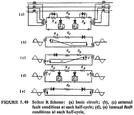
The resistances RA and RB are made slightly greater than that of the pilot loop resistance RP. Under through fault conditions either RA or RB is short circuited by its rectifier depending on the particular half cycle. It can be seen from Fig. (5.40) that neither relay operates as the voltage is negative. During an internal fault both relays have positive voltage during one half-cycle and zero voltage during the other half-cycle.
Protection of Tee’d Feeders. Pilot Wire Protection Relay for tee’d feeders is more difficult than for a single feeder. The currents at each feeder end may differ considerably which results in different loading on the CTs which in turn may lead to out-of-balance currents or voltages and thus result in instability. Hence a vectorial comparison of quantities derived from the several feeder ends is resorted to. In other words, the unit protection of a number of parallel circuits is achieved by comparing the impedances of the several parallel paths. Protection using these principles is known as transverse differential protection.