Leading Power Factor Load:
Suppose the load in Fig. 9.46(a) is capacitive, the wattmeter connected in the leading phase would read less value. In that case, WR will be the lower reading wattmeter, and WY will be the higher reading wattmeter. Figure 9.48 shows the phasor diagram for the Leading Power Factor Load.
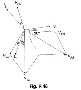
As the Leading Power Factor Load, the phase currents, IR, IY and IB are leading their respective phase voltage by an angle Φ. From Fig. 9.48, the reading of the wattmeter connected in the leading phase is given by
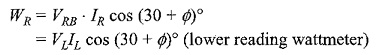
Similarly, the reading of the wattmeter connected in the lagging phase is given by
Again the total power is given by
Hence
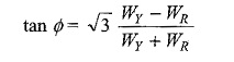
A comparison of this expression with that of lagging power factor reveals the fact that the two wattmeter readings are interchanged, i.e. for lagging power factor, WR is the higher reading wattmeter, and WY is the lower reading wattmeter; where as for leading power factor, WR is the lower reading wattmeter, and WY is the higher reading wattmeter.
While using the expression for power factor, whatever may be the nature of the load, the lower reading is to be subtracted from the higher reading in the numerator.
The variation in the wattmeter reading with the capacitive load follows the same sequence as in inductive load, with a change in the roles of wattmeters.