Frequency Multiplier using PLL 565:
Fig. 2.128 shows the block diagram for a frequency multiplier using PLL 565.
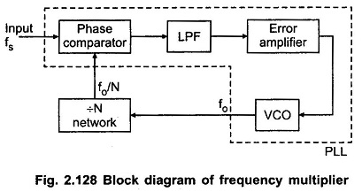
Here , a divide by N network is inserted between the VCO output (pin 4) and the phase comparator input (pin 5). Since the output of the divider is locked to the input frequency fi, the VCO is actually running at a multiple of the input frequency. Therefore, in the locked state, the VCO output frequency fo is given by,
![]()
By selecting proper divider by N network, we can obtain desired multiplication. For example, to obtain output frequency fo = 6 fi ,a divide by N should be equal to 6.
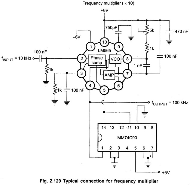
The Fig. 2.129 shows LM 565 IC used as a frequency multiplier circuit. The IC 7490 is a 4 bit binary counter. It is configured as a divide by 10 circuit.