Frequency Multiplier Circuit:
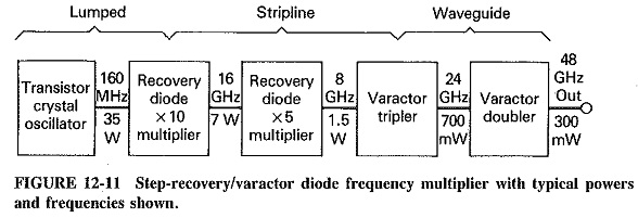
A typical Frequency Multiplier Circuit chain is shown in Figure 12-11, The first stage is a transistor crystal oscillator, operating in the VHF region, and this is the only circuit in the chain to which dc power is applied. The next stage is a step-recovery multiplier by 10, bringing the output into the low-GHz range. This multiplier is likely to have lumped input circuitry and stripline or coaxial output. With 10 X multiplication, the efficiency will be of the order of 20 percent, as shown in Figure 12-11. Another snap-off 5 X multiplier now brings the output into the X band, with comparable efficiency. Normal varactors are used from this point onward. The reason is an increasing difficulty, beyond the X band, in constructing step-recovery diodes with snap-times sufficiently short to meet the 1/fout criterion.
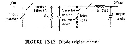
The circuit of Figure 12-12 shows a simple frequency tripler, which could be varactor or step-recovery. It can also be taken as the equivalent of a higher frequency stripline or cavity tripler. Note that the diode bias is provided by resistor RB, in a leak-type arrangement. For correct operation of a snap-off varactor multiplier, the value of the resistance is normally between 100 and 500Ω. No circulator is necessary to isolate input from output, because the two operate at different frequencies, and the filters provide all the isolation required. Note finally that the tripler is provided with an idler circuit, which is a tuned circuit operating at the Frequency Multiplier Circuit of fout – fin. Idlers are further discussed in conjunction with parametric amplifiers.
Performance, Comparison and Applications:
Snap-off varactors multiply by high factors with better efficiency than ordinary varactor chains, and so they are used by preference where possible. Varactors produce higher output, powers from about 10 GHz, and step-recovery diodes are not available for frequencies above 20 GHz, while varactors can be used well above 100 GHz. Snap-off devices are suitable for comb generators, whereas the others are not. It has been found that varactor diodes are preferable to step-recovery diodes for broadband Frequency Multiplier Circuit. These are circuits in which the input frequency may occur anywhere within a bandwidth of up to 20 percent, and any such frequency must be multiplied by a given factor.
Step-recovery diodes are available for power outputs in excess of 50 W at 300 MHz, through 10 W at 2 GHz to 1 W at 10 GHz. Multiplication ratios up to 12 are commonly available, and figures as high as 32 have been reported. Efficiency can be in excess of 80 percent for triplers at frequencies up to 1 GHz. With an output Frequency Multiplier Circuit of 12 GHz, 5 X multiplier efficiency drops to 15 percent.
For varactor diodes, the maximum power output ranges from more than 10 W at 2 GHz to about 25 mW at 100 GHz; most varactors at frequencies above 10 GHz are gallium arsenide. Tripler efficiencies range from 70 percent at 2 GHz to just under 40 percent at 36 GHz, and a GaAs varactor doubler efficiency of 54 percent at 60 GHz has also been reported.
For many years, Frequency Multiplier Circuit chains provided the highest microwave powers available from semiconductors, but other developments have overtaken them. At the lower end of the microwave spectrum, GaAs FETs are capable of higher powers, as are Gunn and IMPATT diodes from about 20 to at least 100 GHz. Unless the highest frequency stabilities are required (note that it is the output of a crystal oscillator that is multiplied), it is more likely that a transistor Gunn or IMPATT oscillator will be used up to about 100 GHz. One of the current applications of multiplier chains is to provide a low-power signal used to phase-lock a Gunn or IMPATT oscillator.
Varactors are used widely for tuning, for frequency-modulating microwave oscillators, and as the active devices in parametric amplifiers, as will be shown in the next section. They are produced by a mature, well-established manufacturing technique, with consequent good reliability and comparatively low prices.
Step Recovery Diodes:
A step-recovery diode, also known as a snap-off varactor, is a silicon or gallium arsenide p-n junction diode, of a construction similar to that of the varactor diode. It is an epitaxial diffused junction diode, designed to store charge when it is conducting with a–forward bias. When reverse bias is applied, the diode very briefly discharges this stored energy, in the form of a sharp pulse very rich in harmonics. The duration of this pulse is typically 100 to 1000 ps, depending on the diode design. This snap time must in practice be shorter than the reciprocal of the output frequency; for example, for an output frequency of 8 GHz, snap time should be less than T = 1/8 X 10-9 = 1.25 X 10-10 = 125 ps.
As will be shown in the next section, a step-recovery diode is biased so that it conducts for a portion of the input cycle. The depletion layer of the junction is charged during this period. When the input signal changes polarity and the diode is biased off, it then produces this sharp pulse, which is very rich in harmonics. All that is then needed in the output is a tuned circuit operating at the wanted harmonic, be it the second or the twentieth. If the circuit is correctly designed, efficiencies well, in excess of 1/n are possible, where n is the frequency multiplication factor. This means that feeding 12 W at 0.5 GHz to a snap-off varactor may result in decidedly more than 1.2 W out at 5 GHz.
It is also possible to use these diodes without a tuned output circuit, to produce multiple harmonics in so-called “comb generators.” Also possible is the stacking of two or more step-recovery (or varactor) diodes in the one package, to provide a higher power-handling capacity.