Signal Generator in Electronic Instrumentation Articles:
What is Signal Generator? A signal generator is a vital component in a test setup, and in electronic troubleshooting and development, whether on a service bench or in a research laboratory. Signal generators have a variety … (Read More)
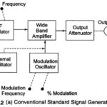
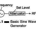
Standard Signal Generator Block Diagram and Working Principle: A standard signal generator produces known and controllable voltages. It is used as power source for the measurement of gain, signal to noise ratio (S/N), bandwidth, standing wave ratio and other properties. It … (Read More)
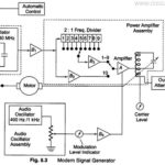
Modern Laboratory Signal Generator Block Diagram and its Working: To improve the frequency stability, a single master oscillator is optimally designed for the highest frequency range and frequency dividers are switched in to produce lower ranges. … (Read More)
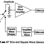
AF Sine and Square Wave Generator: The block diagram of an AF Sine and Square Wave Generator audio oscillator is illustrated in Fig. 8.4. The signal generator is called an oscillator. A Wien bridge oscillator is used in this generator. The Wien … (Read More)
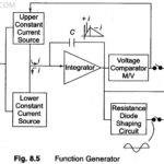
Function Generator Block Diagram: A Function Generator Block Diagram produces different waveforms of adjustable frequency. The common output waveforms are the sine, square, triangular and sawtooth waves. The frequency may be adjusted, from a fraction of a Hertz to several hundred … (Read More)
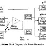
Pulse and Square Wave Generator Block Diagram (Laboratory Type): Pulse and Square Wave Generator are used as measuring devices in combination with a CRO. They provide both quantitative and qualitative information of the system under test. They are made use of … (Read More)
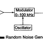
Random Noise Generator Block Diagram and its Working: A simplified Random Noise Generator Block Diagram used in the audio frequency range is shown in Fig. 8.8. The instrument offers the possibility of using a single measurement to indicate performance over a wide … (Read More)
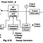
Block Diagram of Sweep Generator: It provides a sinusoidal output voltage whose frequency varies smoothly and continuously over an entire frequency band, usually at an audio rate. The process of frequency modulation may be accomplished … (Read More)
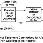
RF Signal Generator: An RF signal generator, when used for alignment and testing of the RF and IF stages of a TV receiver, permits recording of circuit performance at one frequency at a time. Therefore, plotting the total response curve point … (Read More)
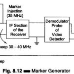
Marker Generator Block Diagram: The sweep generator provides a visual display of the characteristics of the circuit or amplifier, but this is inadequate because it does not give any precise information of the frequency on the traced curve. … (Read More)
Video Test Pattern Generator: A pattern generator provides video signals directly, and with RF modulation, on standard TV channels for alignment, testing and servicing of TV receivers. The output signal is designed to produce simple geometric patterns like vertical and horizontal … (Read More)
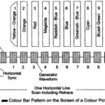
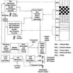
Color Bar Generator: The composite video signal at the output of a video detector consists of luminance Y signals, the chrominance signal, the color burst, sync pulses and blanking pulses. The amplitude of the video signal varies continuously due to the … (Read More)
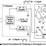
Circuit Connections for Producing a Vectrogram and Lissajous Pattern: This test instrument combines a keyed colour bar generator with an oscilloscope and is used for alignment and testing the colour section of a TV receiver. The amplitude and phase of the … (Read More)
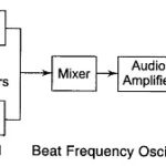
Beat Frequency Oscillator (BFO) | Block Diagram | Working and Limitations: In this Beat Frequency Oscillator, the outputs of two RF oscillators are applied to a square law detector and the resulting difference frequency is amplified. The main advantage of this … (Read More)