Bridges in Electronic Instrumentation Articles:
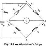
Wheatstone Bridge Diagram: A Wheatstone Bridge diagram in its simplest form consists of a network of four resistance arms forming a closed circuit, with a dc source of current applied to two opposite junctions and a current detector connected to the … (Read More)
Kelvins Bridge and Kelvins Double Bridge: When the resistance to be measured is of the order of magnitude of bridge contact and lead resistance, a modified form of Wheatstone’s bridge, the Kelvins Bridge is employed. Kelvins Bridge is a modification of Wheatstone’s … (Read More)
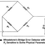
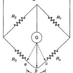
Bridge Controlled Error Detection: Whenever a bridge is unbalanced, a potential difference exists at its output terminal. The potential difference causes current to flow through the detector (say, a galvanometer) when the bridge is used as … (Read More)
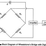
Block Diagram of Wheatstones Bridge with Digital Readout: The tremendous increase in the use of digital circuitry has had a marked effect on electronic test instruments. The early use of digital circuits in bridges was to provide a Digital Readout. The actual measuring … (Read More)
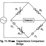
Comparison Bridge: There are two types of Comparison Bridge, Namely Capacitance Comparison Bridge Inductance Comparison Bridge 1. Capacitance Comparison Bridge: Figure 11.18 shows the circuit of a capacitance comparison bridge. The ratio arms R1, R2 are resistive. The known standard capacitor C3 is in series … (Read More)
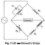
Maxwell Bridge Theory: Maxwell Bridge theory, shown in Fig. 11.21, measures an unknown inductance in terms of a known capacitor. The use of standard arm offers the advantage of compactness and easy shielding. The capacitor is almost a loss-less component. One … (Read More)
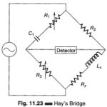
Hays Bridge Circuit: Hays Bridge Circuit, shown in Fig. 11.23, differs from Maxwell’s bridge by having a resistance R1 in series with a standard capacitor C1 instead of a parallel. For large phase angles, R1 needs to be low; therefore, this bridge … (Read More)
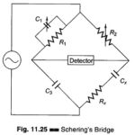
Measurement of Capacitance using Schering Bridge: A very important bridge used for the precision measurement of capacitors and their insulating properties is the Schering Bridge Experiment. Schering Bridge basic circuit arrangement is given in Fig. 11.25. The standard capacitor C3 is a … (Read More)
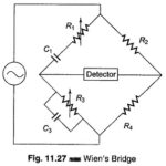
Wien Bridge Circuit Diagram: The Wien Bridge Circuit Diagram shown in Fig. 11.27 has a series RC combination in one arm and a parallel combination in the adjoining arm. Wien’s bridge in its basic form, is designed to measure frequency. It … (Read More)
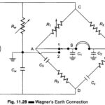
Wagner Ground Connection: When performing measurements at high frequency, stray capacitances between the various bridge elements and ground, and between the bridge arms themselves, become significant. This introduces an error in the measurement, when small values of … (Read More)
Detectors Types: The Detectors Types are as follows For low frequency, the most convenient detector is the vibration galvanometer. For ordinary laboratory work at frequencies up to a few 100 Hz, the moving coil type of instrument is usually employed. It has a high … (Read More)
Microprocessor Controlled Bridge: Digital computers have been used in conjunction with test systems, bridges, and process controllers for several years. In these applications, computers were used to give instructions and perform operations on the data measured. When … (Read More)
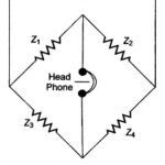
AC Wheatstone Bridge: Impedances at AF or RF are commonly determined by means of an ac Wheatstone bridge. The diagram of an ac bridge is given in Fig. 11.17. This bridge is similar to a dc bridge, except that the bridge arms … (Read More)
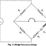
Resonance Bridge for Measurement of Inductance or Capacitance: One arm of this Resonance Bridge, shown in Fig. 11.29, consists of a series resonance circuit. The series resonance circuit is formed by Rd, Cd and Ld in series. All the other arms … (Read More)