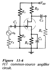
Frequency Response of FET Amplifier
Frequency Response of FET Amplifier: Low-Frequency Response - The low Frequency Response of FET Amplifier circuits is determined by exactly the same considerations as for BJT circuits. The lower cutoff frequency is normally set by…
Comments Off on Frequency Response of FET Amplifier
February 20, 2019