Bus Impedance Matrix Method for Analysis of Unsymmetrical Shunt Faults:
Bus Impedance Matrix Method of fault analysis, given for symmetrical faults can be easily extended to the case of unsymmetrical faults. Consider for example an LG fault on the rth bus of a n-bus system. The connection of sequence networks to simulate the fault is shown in Fig. 11.25.
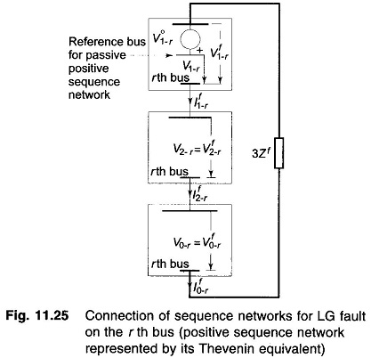
The positive sequence network has been replaced here by its Thevenin equivalent, i,e. prefault voltage V°1-r, of bus r in series with the passive positive sequence network (all voltage sources short circuited). Since negative and zero sequence prefault voltages are zero, both these are passive networks only.
It may be noted that subscript a has been dropped in sequence currents and voltages, while integer subscript is introduced for bus identification. Superscripts o and f respectively, indicate prefault and postfault values.
For the passive positive sequence network
![]()
where
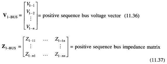
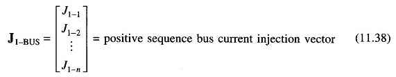
and
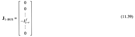
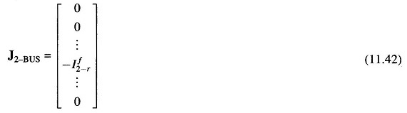
As per the sequence network connection, current –If1-r is injected only at the faulted rth bus of the positive sequence network, we have therefore
Substituting Eq. (11.39) in Eq. (11.35), we can write the positive sequence voltage at the rth bus of the passive positive sequence network as
![]()
Thus the passive positive sequence network presents an impedance Z1-rr to the positive sequence current If1-r.
For the negative sequence network
![]()
The negative sequence network is injected with current If2-r at the rth bus only. Therefore,
The negative sequence voltage at the rth bus is then given by
![]()
Thus, the negative sequence network offers an impedance Z2-rr to the negative sequence current If2-r
Similarly, for the zero sequence network
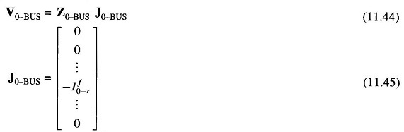
and
![]()
That is, the zero sequence network offers an impedance Z0-rr to the zero sequence current If0-r.
From the sequence network connection of Fig. 11.25, we can now write
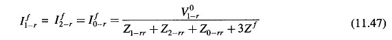
Sequence currents for other types of faults can be similarly computed using Z1-rr, Z2-rr and Z0-rr in place of Z1, Z2 and Z0 with Ea = V°1-r.
Postfault sequence voltages at any bus can now be computed by superposing on prefault bus voltage, the voltage developed owing to the injection of appropriate sequence current at bus r.
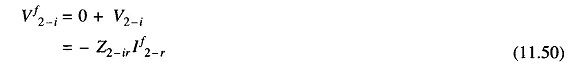
For passive positive sequence network, the voltage developed at bus i owing to the injection of -If1-r at bus r is
![]()
Hence postfault positive sequence voltage at bus i is given by
![]()
where
- V°1-i = prefault positive sequence voltage at bus i
- Z1-ir = irth component of Z1-BUS
Since the prefault negative sequence bus voltages are zero, the postfault negative sequence bus voltages are given by
where
- Z2-ir = irth component of Z2-BUS
Similarly, the postfault zero sequence bus voltages are given by
![]()
where
- Z0-ir = irth component of Z0-BUS
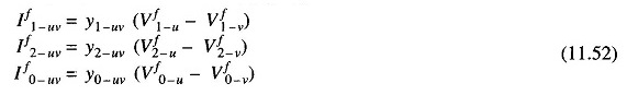
With postfault sequence voltages known at the buses, sequence currents in lines can be computed as:
For line uv, having sequence admittances Y1-uv, Y2-uv and Y0-uv
Knowing sequence voltages and currents, phase voltages and currents can be easily computed by the use of the symmetrical component transformation

It appears at first, as if this method is more laborious than computing fault currents from Thevenin impedances of the sequence networks, as it requires computation of Bus Impedance Matrix Method of all the three sequence networks. It must, however, be pointed out here that once the bus impedance matrices have been assembled, fault analysis can be conveniently carried out for all the buses, which, in fact, is the aim of a fault study. Moreover, Bus Impedance Matrix Method can be easily modified to account for changes in power network configuration.