Common Base Circuit Diagram
Common Base Circuit Diagram: The Common Base Circuit Diagram (CB) shown in Fig. 6-34 is very similar to a CE circuit, except that the input signal is applied to the…
Continue Reading
Common Base Circuit Diagram
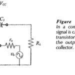
Common Base Circuit Diagram: The Common Base Circuit Diagram (CB) shown in Fig. 6-34 is very similar to a CE circuit, except that the input signal is applied to the…
Switching Circuits (Multivibrators) Interview Questions and Answers: 1. What is an electric switch? Ans. An electric switch is a device that can turn on or off current in an electrical circuit.…
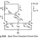
What is Current Mirror? - Circuit Diagram and its Workings The two-transistor current source, also called a current mirror, is the basic building block in the design of integrated circuit…
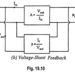
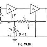
Voltage Shunt Feedback Amplifier Circuit: Voltage Shunt Feedback Amplifier Circuit is also known as shunt-derived shunt fed feedback or voltage shunt inverse feedback. Here, a small portion of the output…
Voltage Series Feedback Amplifier or Shunt Derived Series Fed Feedback Amplifier: Voltage Series Feedback Amplifier Circuit is also called the shunt-derived series-fed feedback. Here the amplifier and feedback network are…
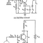
Self Bias or Potential Divider Bias Circuit: This is the most commonly used biasing arrangement. The arrangement of Self Bias or Potential Divider Bias Circuit is shown in Fig. 12.17…
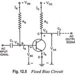
Fixed Bias Circuit Diagram - Advantages and Disadvantages: Fixed Bias Circuit Diagram shown in Fig. 12.5 uses two batteries VBB and VCC. The battery VBB gives potential to the base…
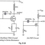
Crystal Oscillators - Circuit, Working, Advantages and Disadvantages: In crystal oscillators, the usual electrical resonant circuit is replaced by a mechanically vibrating crystal. The crystal (usually quartz) has a high…