Current Shunt Feedback Amplifier Circuit:
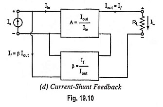
Current Shunt Feedback Amplifier Circuit is also known as series-derived shunt fed feedback or current shunt inverse feedback. In this circuit, the feedback network picks up a part of the output current and produces a feedback voltage in parallel with the input signal voltage, as shown in Fig. 19.10(d). Since the feedback shunts the input so input impedance is reduced with feedback whereas output impedance is increased because of feedback network being in series with the output.
A two-stage cascaded amplifier using such a feedback is given in Fig. 19.41. Here feedback is from the emitter of second stage to the base of first stage through resistor Rf. In this input voltage (Vin2) to second stage is much larger than input voltage (Vin1) to first stage, because of amplifying action of transistor Q1, and is in phase opposition to it (i.e., phase difference of 180°). Voltage Ve2 is only slightly smaller than Vin2, because of emitter follower action. Also voltages Ve2 and Vin2 are in phase. Thus Ve2 is larger in magnitude than Vin1 and has a phase difference of 180° with Vin1. When input signal increases causing Is to increase, feedback current If also increases and so the input current Vin1 would be smaller than it would be without feedback as it is difference of Is and If. Thus negative feedback is provided.
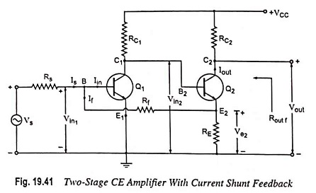
With Rf much larger than RE, the circuit shown in Fig. 19.41 approximates a current-shunt feedback pair and feedback current If is given as
because Vin1 is quite small as compared to Ve2
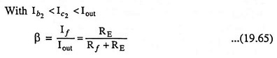
Neglecting base current of transistor Q2 in comparison to its collector current and assuming Rf >> RE
![]()
and so
Since feedback current is proportional to the output current, this circuit is an example of a Current Shunt Feedback Amplifier.
Transfer current gain with feedback,
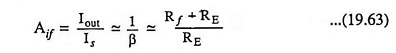
Thus transfer current gain Aif would be stable provided that resistors RE and Rf are stable.
Assuming input impedance with feedback Rinf to be zero, Vs = IsRs
and the voltage gain with feedback,
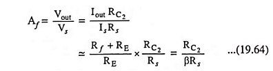
Thus voltage gain with feedback is stable i.e., independent of the transistor parameters, the temperature, or supply voltage variations because resistors Rf, RE, RC2 and RS are stable elements.
Amplifier Without Feedback:
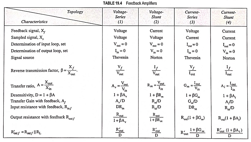
Referring to the fourth topology in Table 19.4, the input circuit of the amplifier without feedback is obtained by opening the output loop at the emitter of Q2. This places Rf in series with RE from base to emitter of Q1. The output circuit is obtained by shorting the input node (base of Q1). This places Rf in parallel with RE. The resultant equivalent circuit is shown in Fig. 19.42. Since the feedback signal is a current, the source is represented by a Norton’s equivalent circuit with
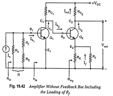
![]()
The feedback signal is the current If in the resistor Rf, which is in the output circuit.
From Fig. 19.42,
which is in agreement with Eq. (19.62).