Development of Airblast Circuit Breaker:
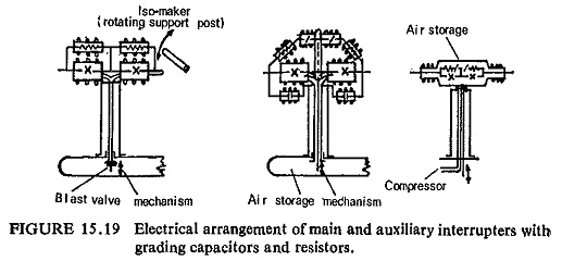
The development of Airblast circuit breakers has taken place in three stages shown schematically in Fig. (15.19):
- Momentarily pressurized Airblast breakers with isomaker in the
- Momentarily pressurized air-blast breakers with isomaker in separate pressurized chamber.
- Permanently pressurized air-blast breakers with isomaker in separate pressurized chambers.
In the first design air-blast valve is placed inside the storage tank at earth potential and the contacts are separated by the air pressure acting against a spring. The blast is removed after about 100 ms and the contacts reclose. An isomaker arm opens in free air about 40 ms after the main contacts breaking the current of a few amperes flowing through voltage grading resistors and serve both to isolate and to make the circuit.
The main drawbacks with this type of air-blast breakers are:
- For the highest voltage steps (420, 525, 765 KV) isolators of greater length and therefore of higher inertia must be used. It becomes difficult to give them the high speeds required on breaking and on closing under all atmospheric conditions with a sufficient reliability.
- When the isolator is long it practically becomes impossible to achieve the high speed auto-reclosing feature.
- Compressed air consumption is quite high.
- Due to its weight and general architecture the circuit breaker cannot be suspended.
- The construction design does not lead to the lowest possible cost.
In the second series of Airblast breakers the tripping operation ist secured by admitting compressed air into the interrupter when the main, valve opens. Air activates the piston causing the contacts to open and then extinguish the arc. Exhaust gases are expanded to the atmosphere through the nozzles. A few hundredths of a second later, the valves are closed and the compressed air can now no longer be expelled to the atmosphere. The contacts are held open in compressed air. The circuit breaker can remain in this position indefinitely. For closing, the valve is reclosed and thus the receiver and the interrupter do not communicate with each other. Valves are open which in turn depressurize the interrupter. Drawn back by its springs, the moving contact closes.
The advantages of this arrangement over the first series of air-blast breakers are:
- The circuit breaker is generally light because of the elimination of heavy series isolator.
- The isolator is no longer a hindrance to reach extra high voltages., By mounting 2, 3, 4 or 8 interrupters in series it is possible to build circuit breakers for 100, 170, 245, 420, 525, 735 KV.
- Since closing and opening operations utilize only low inertia parts, high speed auto-reclosures with dead times of about 0.03s are possible.
- The higher weight and smaller size makes it possible easily to build interrupting elements for either supported or suspended installation.
The disadvantages of this series are:
- Emptying the interrupters on every closing operation entails a high compressed air consumption, since for the subsequent tripping operation the corresponding dead volume must be filled again. Furthermore the closing time is too long.
- When the circuit breaker comprises a number of interrupters per pole the existence of main valve imposes that these interrupters are arranged symmetrically with respect to the valve so that compressed air supply is perfectly balanced. Consequently there is an important restraint in the architecture of the circuit breaker. For instance, it is not easy to achieve a circuit breaker with 3 or 4 interrupters mounted vertically one over the other and to have the circuit breaker occupy the minimum space area.
- On tripping, the pressure in the interrupter does not reach its maximum value forthwith and thus the blast is not fully utilized when the contacts begin to part.
In the third series of Airblast breakers the compressed air is always stored in interrupters at 100% of the rated value. The tripping operation is secured by an auxiliary relay which opens the exhaust valves first and then followed by the opening of the contacts. A few ms later the exhaust valves reclose whereas the contacts are held open. On closing, the contacts are closed by the depressurizing action whereas the valves remain still closed.
The main advantages of this series of Airblast breakers over the previous designs are:
- As the air pressure in the chamber is always at full rated value, full efficiency is realized thus ensuring large breaking capacities.
- On account of the above reason the build up of dielectric strength across contacts immediately after their separation is greatly improved.
- Air consumption is extremely low because only a small quantity of air is exhausted and the chambers are not to be recharged to the full On account of this air consumption and acoustic energy due to the exhaust of air are extremely low.
- Owing to better dielectric properties of compressed air and the rated pressure at the time of contact separation the breaking capacity of each chamber increases, thus reducing the number of breaks per phase and also reducing the maintenance and overall dimensions.
- Owing to the permanently pressurized design the erosion by the preliminary spark during closing operation is considerably reduced.
- Since the contacts are surrounded by the high pressure medium that is a good conductor of heat the rated normal current rating can be raised up to 2000 A without any difficulty.
- Low weight of complete breaker and absence of ground shocks permits installation any where and substantially reduces foundation costs.
The most recent modular designs extend the above principles, while higher pressures (about 6MN/m2) and the use of low value damping resistors about 400 ohms per pole permits a halving of the required number of interrupters. The module, which contains two main and two auxiliary interrupters and two resistors, also serves for compressed air storage, and replaces four interrupters of the older design. Silencers are an integral part of the design. Fault clearance can be attained within 30-40 ms.