Transistor Models and Parameters:
T-Equivalent Circuit – Because a transistor consists of two pn-junctions with a common centre block, it should be possible to use two pn-junction ac equivalent circuits as the Transistor Models and Parameters. Figure 6-9 shows the ac equivalent circuit for a transistor connected in common-base configuration. Resistor re represents the BE junction resistance, rc represents the CB junction resistance, and rb represents the resistance of the base region which is common to both junctions. Junction capacitances CBE and CBC are also included.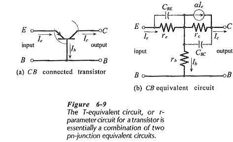
If the Transistor Models and Parameters equivalent circuit is simply left as a combination of resistances and capacitances, it could not account for the fact that most of the emitter current flows out of the collector terminal as collector current. To represent this, a current generator is included in parallel with rc and CBC. The current generator is given the value αIe, where, α = Ic/Ie.
The complete circuit is known as the T-equivalent circuit, or the r-parameter equivalent circuit. The equivalent circuit can be rearranged in common-emitter or common-collector configuration.
The currents in Fig. 6-9 are designated Ib, Ic, and Ie (instead of IB,IC, and IE) to indicate that they are ac quantities rather than dc. The circuit parameters rc, rb, re, and α, are also ac quantities.
r-Parameters:
Referring to Fig. 6-9, re represents the ac resistance of the forward-biased BE junction, so it has a low resistance value, (typically 25 Ω). The resistance of the reverse-biased CB junction (rc) is high, (typically 100 kΩ to 1 MΩ). The base region resistance (rb) depends upon the doping density of the base material. Usually, rb ranges from 100 Ω to 300 Ω.
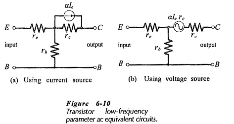
CBE is the capacitance of a forward-biased pn-junction, and CBC is that of a reverse-biased junction. At medium and low frequencies the junction capacitances may be neglected. Instead of the current generator (αIe) in parallel with rc, a voltage generator (αIerc) may be used in series with rc. Two transistor r-parameter models are shown in Fig. 6-10.
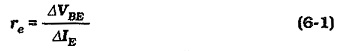
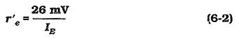
Determination of re:
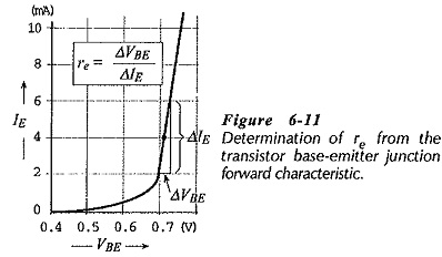
Because re is the ac resistance of the BJT forward-biased base-emitter junction, it can be determined from a plot of IE versus VBE. As illustrated in Fig. 6-11,
This is similar to the determination of the dynamic resistance (rd) for a forward-biased diode. Also like the case of a diode, the ac resistance for the transistor BE junction can be calculated in terms of the current crossing the junction.
As in the case of r′d for a diode, r’e does not include the resistance of the device semiconductor material. Consequently, r’e is slightly smaller than the actual measured value of re for a given transistor.
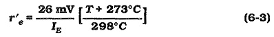
Equation 6-2 applies only to transistors at a temperature of 25°C. For determination of r’e at higher or lower temperatures, the equation must be modified.
h-Parameters:
It has been shown that Transistor Models and Parameters circuits can be represented by an r-parameter or T-equivalent circuit. In circuits involving more than a single transistor, analysis by r-parameters can be virtually impossible. The hybrid parameters, or h-parameters are much more convenient for circuit analysis. These are used only for ac circuit analysis, although dc current gain factors are also expressed as It-parameters. Transistor h-parameter models simplify transistor circuit analysis by separating the input and output stages of a circuit to be analyzed.
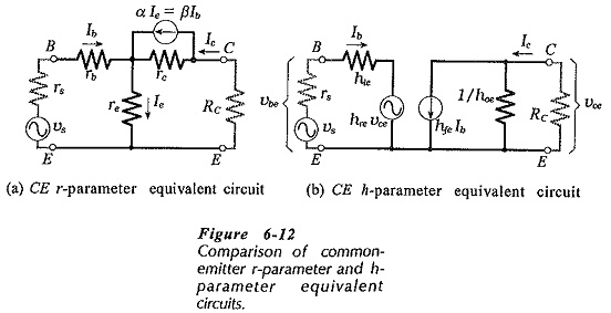
In Fig. 6-12 a common-emitter h-parameter equivalent circuit is compared with a common-emitter r-parameter circuit. In each case an external collector resistor (RC) is included, as well as a signal source voltage (vs) and source resistance (rs). Note that the output current generator in the r-parameter circuit has a value of αIe, which equals βIb.
The input to the h-parameter circuit is represented as an input resistance (hie) in series with a voltage source (hreυce). Looking at the r-parameter circuit, it is seen that a change in output current Ic causes a voltage variation across re. This means that a voltage is fed back from the output to the input. In the h-parameter circuit this feedback voltage is represented as the portion hre of the output voltage υce. The parameter hre is appropriately termed the reverse voltage transfer ratio.
The output of the h-parameter circuit is represented as an output resistance (1/hoe) in parallel With a current generator (hfeIb), where Ib is the (input) base current. So, hfeIb is produced by the input current Ib, and it divides between the device output resistance 1/hoe and the collector resistor RC. Ic is the current passed to RC. This compares with the r-parameter equivalent circuit, where some of the generator current (βIb) flows through rc. The current generator parameter (hfe) is termed the forward transfer current ratio. The output conductance is hoe, so that 1/hoe is a resistance.
rπ Equivalent Circuit:
An approximate h-parameter model for a transistor CE circuit is shown in Fig. 6-13(a). In this case, the feedback generator (hreυce in Fig. 6-12(b)) is omitted. The effect of hreυce is normally so small that it can be neglected for most practical purposes.
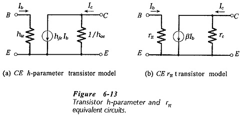
The approximate h-parameter circuit is reproduced in Fig. 6-13(b) with the components labelled as r-parameters; rπ = hie, βIb = hfeIb, and rc =1/hoe. This circuit, known as a hybrid-π model, is sometimes used instead of the h-parameter circuit.
Definition of h-Parameters:
The e in the subscript of hie identifies the parameter as a common-emitter quantity, and the i signifies that it is an input resistance. Common-base and common-collector input resistances are designated hib and hic, respectively.
As an ac input resistance, hie can be defined as the ac input voltage divided by the ac input current.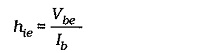
This is usually stated as,
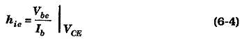
This means that the collector-emitter voltage (VCE) must remain constant when hie is measured.
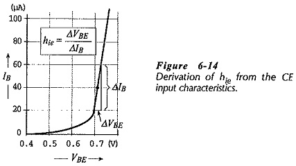
The input resistance can also be defined in terms of changes in dc levels;
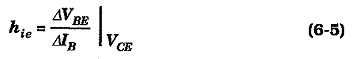
Equation 6-5 can be used for determining hie from the transistor common-emitter input characteristics. As illustrated in Fig. 6-14, ΔVBE and ΔIB are measured at one point on the characteristics, and hie is calculated.
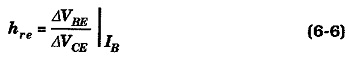
The reverse transfer ratio hre can also be defined in terms of ac quantities, or as the ratio of dc current changes. In both cases, the input current (IB) must be held constant.
The forward current transfer ratio hfe can similarly be defined in terms of ac quantities, or as the ratio of dc current changes. In both cases, the output voltage (VCE) must be held constant.
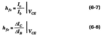
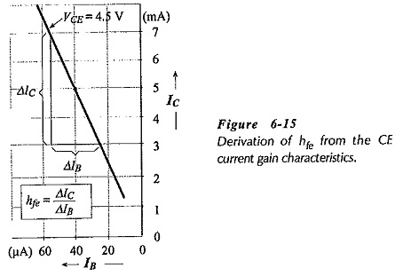
Equation 6-8 can be used to determine hfe from the CE current gain characteristics. Figure 6-15 shows the measurement of ΔIC and ΔIB at one point on the characteristics for the hfe calculation.
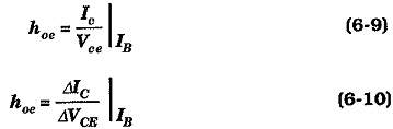
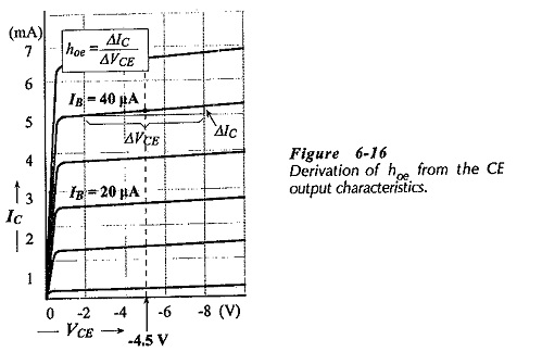
The output conductance, hfe, is the ratio of ac collector current to ac collector-emitter voltage, and its value can be determined from the common emitter output characteristics (see Fig. 6-16).
Common-Base and Common-Collector h-Parameter:
The common-base and common-collector h-parameters are defined similarly to common-emitter h-parameters. They may also be derived from the CB and CC characteristics. Common-base parameters are identified as hib, hfb, etc., and common-collector parameters are designated hic, hfc, and so on.
Parameters Relationships:
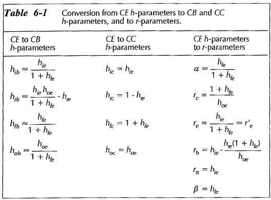
Device manufacturers do not list the values of all parameters on transistor data sheets. Usually, only the CE h-parameters are stated. However, CB and CC h-parameters can be determined from the CE h-parameters. r-parameters can also be calculated from the CE h-parameters. Table 6-1 shows the parameter relationships.