Three Wire DC System Balancer Set:
Although in a 3-wire d.c. system every effort is made to distribute the various loads equally on both sides of the neutral, yet it is difficult to achieve the exact balance. The result is that some current does flow in the neutral wire and consequently the voltages on the two sides of the neutral do not remain equal to each other. In order to maintain voltages on the two sides of the neutral equal to each other, a Three Wire DC System Balancer Set is used.
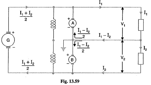
Circuit details Fig. 13.59 shows the use of a balancer set in a Three Wire DC System Balancer Set. The balancer consists of two identical shunt wound machines A and B coupled mechanically and having their armature and field circuits connected in series across the outers. The neutral wire is connected to the junction of the armatures as shown. The circuit arrangement has two obvious advantages. Firstly, only one generator (G) is required which results in a great saving in cost. Secondly, the balancer set tends to equalize the voltages on the two sides of the neutral.
Theory: Since the speeds and field currents of the two machines are equal, their back e.m.f.s have the same value. When the system is unloaded or when the loads on the two sides are the same (i.e. balanced), no current flows in the neutral wire. Hence, the two machines run as unloaded motors
When the load is unbalanced, the current supplied by the +ve outer will be different from that supplied by the negative outer. Suppose that load I1 on the +ve outer is greater that the load I2 on the -ve outer. Since the +ve side is more heavily loaded, p.d. on this side tends to fall below the e.m.f. of the Three Wire DC System Balancer Set. Therefore, machine A runs as a generator. On the other hand, p.d. on the lightly loaded -ve side rises above the e.m.f. of the balancer so that machine B runs as a motor. The result is that energy is transferred from lightly loaded side to the heavily loaded side, preventing the voltage across heavily loaded side form dropping very much below the normal value.
For the condition shown in Fig. 13.59, the machine B acts as a motor and machine A as a generator. The out of balance current II – I2 flows through the middle wire towards the balancers. Assuming the internal losses of the two machines to be negligible, then armature currents will be equal. Hence, one-half of the current in neutral i.e. (I1-I2)/2 will flow through each machine as shown.
Let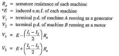
Difference of voltages between two sides
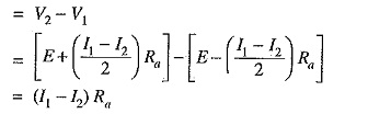
It is clear that difference of voltages between the two sides of the system is proportional to
- the out-of-balance current I1 – I2
- the armature resistance of balancer
Therefore, in order to keep the voltages on the two sides equal, Ra is kept small and loads are arranged on the two sides in such a way that out of balance current is as small as possible.
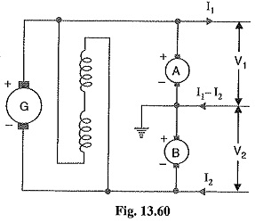
The difference of voltages (V2 — V1) on the two sides can be further reduced by cross-connecting the shunt fields of the Three Wire DC System Balancer Set as shown in Fig. 13.60. As the generating machine A draws its excitation from lightly loaded side which is at a higher voltage, therefore, induced e.m.f. of the machine is increased. On the other hand, induced e.m.f. of machine B is decreased since it draws its excitation from the heavily loaded side. The result is that the difference V2 — V1 is decreased considerably. It may be noted that a perfect balance cannot be obtained because the operation of the Three Wire DC System Balancer Set depends upon a slight unbalancing of the voltages on the two sides.