Synchronous Machine Working Principle:
Figure 5.2 shows the simplified version of an ac Synchronous Machine Working Principle with a 2-pole field winding on the rotor and a single coil aa’ on the stator. This type of rotor poles are known as salient (projecting) poles; and are excited by means of dc fed to the concentrated field winding. The current is fed to the rotor via two slip-rings and carbon brushes as shown already.
Figure 5.2 also shows two mean paths of magnetic flux (shown dotted). The magnetic neutral regions are located in the interpolar gaps. Without any significant loss of accuracy, the reluctance of the iron path will be neglected.

Assuming that the air-gap over the pole-shoes is uniform, the flux density in the gap over the pole-shoes is constant (as mmf acting along any flux path is constant for the concentrated field winding); the flux density in the air layer along the stator periphery gradually falls off to zero in the interpolar region.
The result is a flat-topped flux density wave as shown in Fig. 5.3. Since the magnetic flux enters the stator normally, the relative movement between the stator conductors (coil-sides of the stator coil) and the air-gap flux density is mutually perpendicular. This results in the emf being induced along the stator conductors as per the Blv rule, with emf direction on being governed by v x B or the Fleming’s right-hand rule. It is to be further observed that the magnetic field has symmetry along the axial length; the end effects (fringing) at either end of the cylindrical structure are neglected in this model.

In ac machines it is desirable for the induced emfs to be sinusoidal in waveform, therefore, flux density wave in the machine air-gap must be sinusoidal. This is achieved in the salient pole construction (with concentrated field coils) by providing nonuniform air-gap above pole-shoes; minimum air-gap in the middle of the pole-shoe progressively increasing towards outer edges. Here it will be assumed the air-gap flux density wave is perfectly sinusoidal as shown in Fig. 5.4.

Another method of obtaining a sinusoidal B-wave in air-gap is the use of the nonsalient pole structure, i.e. a cylindrical rotor with uniform air-gap but with a suitably distributed field winding along the rotor periphery as shown in Fig. 5.5. In this structure as one moves away from the pole-axis, the flux paths link progressively smaller number of field ampere-turns. The ampere-turns can be so distributed as to give a nearly sinusoidal B-wave in space as shown in Fig. 5.4.

The armature coil in the elementary 2-pole machine of Fig. 5.2 is placed in two diametrically opposite slots notched out on the inside of the stator. The coil can have many turns. Various shapes of coils are employed; Fig. 5.6 shows a diamond-shaped coil. Each coil has two sides termed coil sides. The active length of coil-sides equals the magnetic length of the stator over which the B-wave acts to induce emf. No emf is produced in end connections which are suitably formed so as to be neatly accommodated on the stator ends away from the rotating parts.
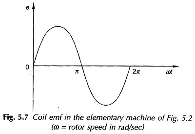
The two coil-sides of our elementary machine are shown in the cross-sectional developed diagram of Fig. 5.4. Since the coil-sides are 1/2 B-wave length (π radians) apart, the voltages induced in the two coil-sides (Blv, where v is the peripheral velocity of the pole-faces) are identical in value but opposite in sign so that the total coil voltage is double the coil-side voltage and has the same waveform as the B-wave and is shown in Fig. 5.7. One cycle of the alternating emf is generated in one revolution of the rotor.

Consider now a machine with a 4-pole structure, as shown in Fig. 5.8, the poles being alternately north and south. The flux-density space wave of this structure is drawn in Fig. 5.9. It has two complete cycles in the total angle of 2π radians which will now be referred to as the mechanical angle. It is obvious from Figs. 5.8 and 5.9 that now two coils can be placed symmetrically—one coil under each pair of poles. Each coil has a span (pitch) of 1/2 B-wave length and the axes of the two coils are spaced one full B-wave length apart. It is immediately seen that magnetic and electrical conditions existing under one pair of poles are merely repeated under every other pole-pair.
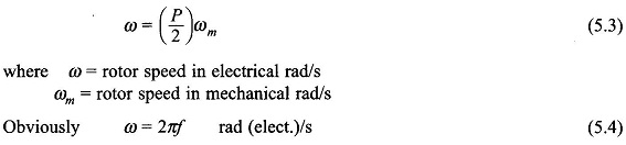
The emf’s induced in coils a1a′1 and a2a′2 are both alternating, equal in magnitude and in time phase to each other. It is convenient to work in terms of one pole pair of a multi-polar machine (number of poles must obviously be even). The total angular span of one pole pair is therefore taken as 2π and is referred to as electrical angle as different from the actual mechanical angle. Let


These angles are both shown in Fig. 5.9. Taking the ratio of total electrical and mechanical angles of a P-pole machine,
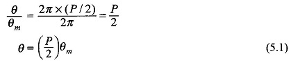
The span of the coil, called the coil-pitch or coil-span, which was indicated to be 1/2 B-wavelength, will be π rad (180°) in electrical angle and is fixed irrespective of the number of machine poles. Such a coil is called full-pitched. For the time being, it will be assumed that all coils are full-pitched. Short-pitched (chorded) coils, i.e., coils with angular span less than 180° elect. are also employed.
In a P-pole machine, one cycle of alternating emf is generated in each coil as one pole-pair of the rotor poles glides past the stator. Thus for one complete revolution of the rotor, P/2 cycles of emf are generated in the coil. Therefore, the frequency of the voltage wave (it is a time wave) is
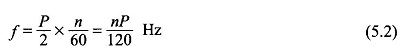
where
n = speed of the rotor in revolution per minute (rpm)
Differentiating each side of Eq. (5.1) with respect to time
The two coils of the 4-pole generator Synchronous Machine Working Principle of Fig. 5.8 are seats of identical emfs and can be connected in series or parallel as shown in Fig. 5.10(a) and (b). The series connection gives double the voltage of one coil and can handle the same maximum current as any one coil. The parallel connection has the same voltage as that of each coil and has twice the maximum current-carrying capacity of one of the coils. The designer exploits the series-parallel arrangement of coil groups to build a machine of desired voltage and current rating.
