Summing Differentiator Circuit:
Summing Differentiator Circuit – Similar to the summing integrator, summing can be obtained using the basic differentiator Circuit. It can be obtained by applying more than one input to the basic differentiator Circuit as shown in the Fig. 2.50.
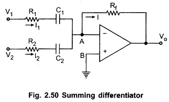
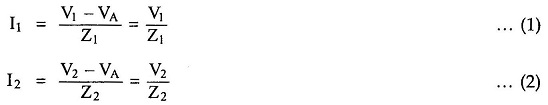
The node B is grounded, hence potential of A is also zero. So VA = 0. Hence we can write the expressions for the various currents as,
and

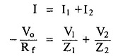
Applying at node A,
Taking of the Equation,

where

and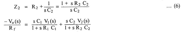
i.e.
![]()
As Rf C1 is very much higher than R1C1 and R2 C2, we get,
![]()
Replacing s by d/dt,
For C1 = C2 we get,
 The expression shows that the output is the sum of the differentiations of the two inputs. Hence the circuit is called as Summing Differentiators.
The resistance R1 is introduced to provide closed loop stability at high frequency and to reduce the high frequency noise.