Reactance Properties of Transmission Lines:
Reactance Properties of Transmission Lines : Just as a suitable piece of transmission line may be used as a transformer, so other chosen transmission-line configurations may be used as series or shunt inductive or capacitive reactances. This is very advantageous indeed. Not only can such circuits be employed at the highest frequencies, unlike LC circuits, but also they are compatible with Reactance Properties of Transmission Lines.
Open and Short Circuited lines as tuned circuits:
The input impedance of a quarter-wave piece of transmission line, short-circuited at the far end, is infinity, and the line has transformed a short circuit into an open circuit. This applies only at the frequency at which the piece of line is exactly λ/4 in length. At some frequency near this, the line will be just a little longer or shorter than λ/4, so that at this frequency the impedance will not be infinity. The further we move, in frequency, away from the original, the lower will be the impedance of this piece of line. We therefore seem to have a parallel-tuned circuit, or at least something that behaves as one. Such a line is often used for this purpose at UHF, as an oscillator tank circuit or in other applications.
If the quarter-wave line is open-circuited at the far end, then, by a similar process of reasoning, a series-tuned circuit is obtained. Similarly, a short-circuited half-wave line will behave as a series-tuned circuit, in the manner described in the preceding section. Such short- or open-circuited lines may be employed at high frequencies in place of LC circuits. In practice, short-circuited lines are preferred, since open-circuited lines tend to radiate.
Properties of lines of various lengths:
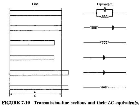
Restating the position, we know that a piece of transmission line λ/4 long and short-circuited at the far end (or λ/2 long and open-circuited at the far end) looks like an open circuit and behaves exactly like a parallel-tuned circuit. If the frequency of operation is lowered, the shunt inductive reactance of this tuned circuit is lower and the shunt capacitive reactance is higher. Inductive current predominates, and therefore the impedance of the circuit is purely inductive. Now, this piece at the new frequency is less than A/4 long, since the wavelength is now greater and the length of line is naturally unchanged. We thus have the important property that a short-circuited line less than λ/4 long behaves as a pure inductance. An open-circuited line less than λ/4 long appears as a pure capacitance. The various possibilities are shown in Figure 7-10, which is really a table of various line lengths and terminations and their equivalent LC circuits.
Stubs:
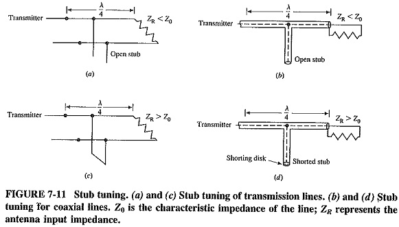
If a load is connected to a transmission line and matching is required, a quarter-wave transformer may be used if ZL is purely resistive. If the load impedance is complex, one of the ways of matching it to the line is to tune out the reactance with an inductor or a capacitor, and then to match with a quarter-wave transformer. Short-circuited transmission lines are more often used than lumped components at very high frequencies; a transmission line so used is called a stub (see Figure 7-11).
The procedure adopted is as follows:
- Calculate load admittance.
- Calculate stub susceptance.
- Connect stub to load, the resulting admittance being the load conductance G.
- Transform conductance to resistance, and calculate Z′0 of the quarter-wave transformer as before.
Impedance variation along a mismatched line:
When a complex load is connected to a transmission line, standing waves result even if the magnitude of the load impedance is equal to the characteristic impedance of the line. If zL is the normalized load impedance, then as impedance is investigated along the line, zL will be measured λ/2 away from the load, and then at successive λ/2 intervals when the line is lossless.
A normalized impedance equal to yL will be measured λ/4 away from the load (and at successive λ/2 intervals from then on). If zL = r + jx, the normalized impedance measured λ/4 farther on will be given by

The normalized load impedance was inductive, and yet, from Equation (7-14), the normalized impedance seen λ/4 away from the load is capacitive. It is obvious that, somewhere between these two points, it must have been purely resistive. This point is not necessarily λ/8 from the load, but the fact that it exists at all is of great importance. The position of the purely resistive point is very difficult to calculate without a chart such as the Smith chart previously mentioned. Many Reactance Properties of Transmission Lines calculations are made easier by the use of charts, and none more so than those involving lines with complex loads.