Application of Variable Speed Drives:
Several drives are driven at constant speeds by induction or synchronous motors, although operation of Application of Variable Speed Drives could lead to saving of substantial amount of energy. Such practice was adapted in the past because of nonavailability of efficient methods of speed control of induction and synchronous motors.
One prominent example of such a case is pump drives where fluid flow control is required. These pump drives have Application of Variable Speed Drives in several industries such as chemical plants, petrochemical plants, refineries, boilers and so on. The drive ratings range up to several megawatts. Earlier the pumps were run at a constant speed by induction or synchronous motor and control the fluid flow was obtained by adjustment of opening of valves (by throttling) or by absorbing or bypassing excess output. Such an arrangement is highly inefficient.
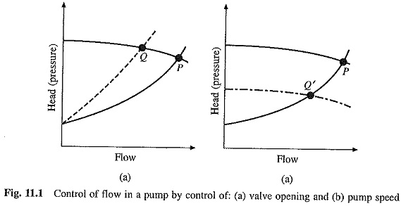
Fig. 11.1(a) shows pump and load characteristics which represent the opposition offered to the flow of fluid through pipes. Load curve has two components: one to lift the fluid to the required height and other to overcome friction. The steady state operating point is obtained where the two curves intersect. The operating point P corresponds to maximum opening of the valve, and therefore, provides maximum flow of fluid. When opening of the valve is reduced, friction component is increased and load curve modifies to that shown by dotted line. Pump and load curve now meet at Q, which is the new operating point.
Note that the flow has reduced but pump head has somewhat increased. When Application of Variable Speed Drives is employed, valve opening is kept at the maximum.
As shown in Fig. 11.1(b), the operating point P is obtained at full speed; which is same as shown in Fig. 11.1(a). When the drive speed is reduced, pump characteristic is shifted down (shown by chain dotted line) but load characteristic is not altered because the valve opening has not changed. The new operating point is Q’, which gives the same fluid flow as point Q (Fig. 11.1(a)) but at a substantially reduced head.
In a pump, the output power is product of the head and fluid flow. Since head is substantially lower at Q’ compared to that at Q, power to be supplied to pump by the drive is substantially lower. Thus, use of Application of Variable Speed Drives can lead to large saving of energy. Studies have shown that the energy saving ranges from 20 to 40% and extra cost incurred in providing speed control can be recovered in a period of 2 – 5 years.
Considering that a number of these drives have ratings in megawatt range, large amount of energy can be saved by the use of Application of Variable Speed Drives.