Synchronous Sequential Circuits or Clocked Sequential Circuits:
In Synchronous Sequential Circuits or clocked sequential circuits, clocked flip-flops are used as memory elements, which change their individual states in synchronism with the periodic clock signal. Therefore, the change in states of flip-flops and change in state of the entire circuit occurs at the transition of the clock signal.
The Synchronous Sequential Circuits or clocked sequential circuits are represented by two models.
Moore Circuit : The output depends only on the present state of the flip-flops
Mealy Circuit : The output depends on both the present state of the flip-flop(s) and on the input (s).
Moore Circuit:
As mentioned earlier, when the output of the sequential circuit depends only on the present state of the flip-flop, the sequential circuit is referred to as Moore Circuit. Let us see one example of Sequential Circuit. Fig. 3.37 shows a sequential circuit which consists of two JK flip-flops and AND gate. The circuit has one input X and one output Y.
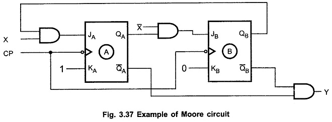
As shown in the Fig. 3.38, input is used to determine the inputs of the flip-flops. It is not used to determine the output. The output is derived using only present states of the flip-flops or combination of it (in this case Y=QAQB).
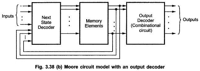
In general form the Moore circuit can be represented with its block schematic as shown in Fig. 3.38 (a) and (b).
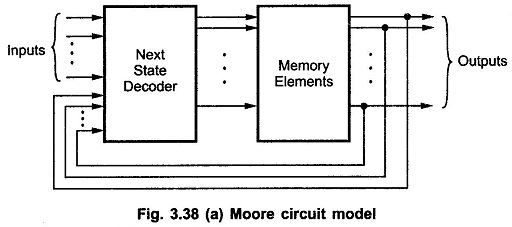
In the Moore Circuit, as output depends only on present state of flip-flops, it appears only after the clock pulse is applied, i.e. it varies in synchronism with the clock input.
Mealy Circuit:
When the output of the sequential circuit depends on both the present state of flip-flop(s) and on the input(s), the sequential circuit is referred to as Mealy Circuit. Fig. 3.39 shows the sample Mealy circuit. As shown in the Fig. 3.39, the output of the circuit is derived from the combination of present state of flip-flops and input (s) of the circuit.
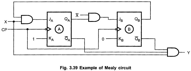
Looking at Fig. 3.39, we can easily realize that, changes in the input within the clock pulses can not affect the state of the flip-flop. However, they can affect the output of the circuit. Due to this, if the input variations are not synchronized with the clock, the derived output will also not be synchronized with the clock and we get false output (as it is a synchronous sequential circuits). The false outputs can be eliminated by allowing input to change only at the active transition of the clock (in our example HIGH-to-LOW).
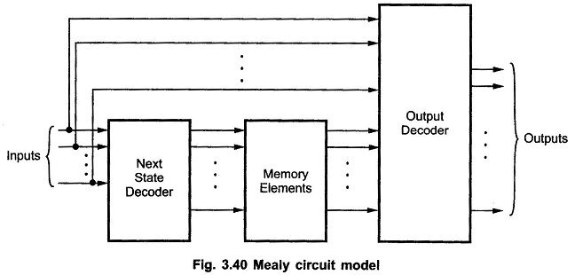
In general form the Mealy circuit can be represented with its block schematic as shown in Fig.3.40.
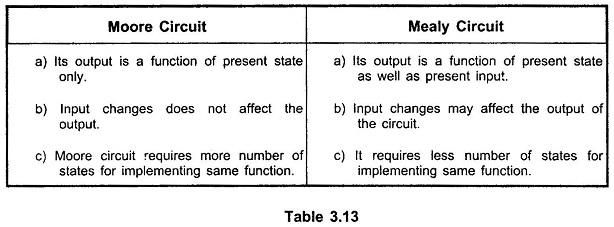
Difference between Moore and Mealy circuit Models: