SF6 circuit breaker:
One of the recent developments in the field of high voltage switchgear is the SF6 circuit breaker. In this a gas called sulphur hexafluoride is used as the medium of insulation and arc interruption.
Basic Features of SF6 Breaker:
SF6 is about 5 times heavier than air. It is chemically very stable, odourless, inert, noninflammable and nontoxic. The gas has a high dielectric strength and outstanding arc-quenching characteristics.
In SF6 the arc voltage remains low until immediately before current zero so that the arc energy does not attain a high value. Moreover the arc time constant for SF6 is also very low. Furthermore, SF6 and its decomposition products are electronegative, permitting electron capture at relatively high temperature. Thus the dielectric strength rises rapidly and enables the breaker to withstand the recovery voltage even under extreme switching conditions. In air-blast circuit breakers air is allowed to escape following the quenching operation. This obviously would be uneconomical in the case of SF6 circuit breaker. Hermetically sealed circuit breaker chambers are therefore developed in which even the gas pressure remains practically constant over long periods. Owing to the low contact erosion in SF6 and almost negligible decomposition of the gas in arc, the breaker can be operated for several years without having to be opened for the purpose of overhauling.
Dielectric Properties of SF6
At atmospheric pressure the dielectric strength of SF6 is about 2.5 times that of air. Actually speaking this value will depend upon the nature of field existing between the electrodes, which in turn will depend on the shape and configuration of electrodes, and the gap between the electrodes. The dielectric strength may actually increase to about 5 times depending upon the nonhomogeneity of the field. Figure (16.10) shows the relation of dielectric strength vs. pressure.

It may be seen from the curves that dielectric strength which is 30% less than that of oil at atmospheric pressure increases rapidly with increase of pressure. It attains a value equal to that of oil at a pressure of 650 gm/cm2 and at a pressure of 1.25 kg/cm2 it is about 15% higher.
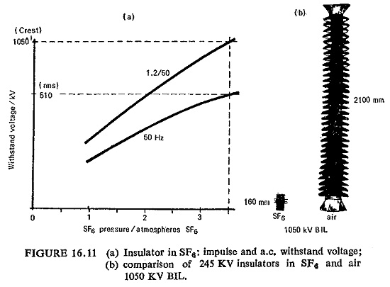
For an insulator with an overall height of 160 mm the impulse and power frequency withstand voltages are shown in Fig. (16.11 a) as a function of the SF6 pressure.
At a pressure of 3.5 atmospheres the withstand voltages are almost equal to those for outdoor post-insulators measuring 2100 mm (Fig. (16.11 b)).
This gas is strongly electronegative, which means that free electrons are readily removed from a discharge by the formation of negative ions through processes by which a free electron is attached to .a neutral gas molecule. The attachment may occur in two ways:
- As direct attachment
![]()
- As dissociative attachment
![]()
The resulting ions which are heavy and relatively immobile are thus ineffective as current carriers so that ionized SF6 has as high an electric strength as unionized gases such as N2 at equal density.
Quencing Properties of SF6
The extinction of a.c. arc at the instant of current zero is primarily influenced by the speed with which the dielectric strength in the contact gap regenerates immediately before and after the passage of current zero.
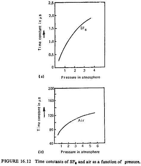
Its efficacy as an arc quenching medium can be explained by the tow dynamic time constant (about 1 μs compared with about 100μs in N2) of arcs drawn in it. In the case of cylindrical arcs, the time constant (H) is a function of the square of arc radius (r). The radius of an arc approaching zero should, therefore, be kept to a minimum.
Now SF6 circuit breaker has a favorable thermal characteristic which is a function of temperature, i.e. the thermal conductivity is low between 3000°K and 7000°K whereas it is high below 3000°K.
The low time constant of SF6 is due to its ability for free electrons to be captured by molecules of SF6 gas. These SF6 ions surround the arc and form an insulating barrier. This reduces the diameter of arc column and hence results in reduction of time constant, which aids arc quenching. Figure (16.12) shows time constants of SF6 and air as functions of pressure.
Conditions are much less favorable where the arc burns in nitrogen. No thin core forms in the critical temperature range between 3000°K and 7000°K because of the good thermal conductivity of nitrogen. The diameter of the arc approaching extinction remains considerably larger and its time constant, which varies as the square of the radius, is therefore, very much greater. The boundary regions below the ionization temperature do not have the same dielectric strength as SF6, because nitrogen is not electronegative. SF6 and almost all its decomposition products are electronegative and have an affinity for electrons. During cooling the dielectric strength of the breaker, therefore, rises more rapidly than, for example, with air.
The influence of low arc time constants on circuit breakers can be seen as follows.
Mayer’s equation for the limiting value of recovery voltage after the current has passed through zero above which arc restrikes is given by
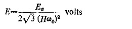
where
Ea = arc voltage.
ω0 = 2πf0 where f0 is the natural frequency of the mains.
H = are time constant.
Since H is 100 times smaller for SF6 than air, for the same value of limiting voltage the natural frequency of mains may be 100 times greater. In other words SF6 circuit breaker can withstand severe RRRV, and thus are most suitable for short line faults without switching resistors, and can interrupt capacitive currents without iestriking.
Behavior of SF6 Gas in ARC:
The high temperature of arc causes all molecular gases, including SF6, to be decomposed into atoms, electrons and ions. These atomic components do not recombine completely to the original SF6 gas on cooling. They form low molecular gaseous sulphur fluorides and compounds with the contact metals, e.g. copper fluorides. Extensive tests have shown that the percentage of gaseous decomposition products is extremely small. These products and any other secondary gaseous reaction products are removed from the gas circuit by filters containing activated aluminium oxide (Al2O3) when the gas is pumped back into the high-pressure tank. The metal fluorides are deposited as a thin nonconductive and harmless layer of fine dust.
Essential Parts of SF6 Breaker:
The essential parts of a SF6 circuit breaker are: (a) the tank, (b) the interrupter units, (c) the operating mechanism, (d) the bushings, and (e) the gas system.
(a) Tank: The distance between line and earthed parts inside the tank is very much reduced due to better insulating properties of SF6. As already illustrated in Fig. (16.11) at 3.5 atmospheres, the dielectric withstands 510 KV at 50 Hz and a 1050 KV BIL test. Even at atmospheric pressure, the insulation distances are sufficient to withstand nearly twice the rated voltage to earth. No large pressure rises are caused due to the operation in SF6, the tanks being designed for a pressure of nearly four times and tested at six times the pressure. Special neoprene gaskets are used in the inspection doors for ensuring protection against leaks. The rotating shaft which transmits mechanical motion to the outside of the tank is sealed by teflon ‘V’ rings which are unaffected by change in ambient temperature.
(b) Interrupter Units: Organic insulation like fibre or micarta should not be located in the arc path since they will be decomposed thus diluting the Teflon which is resistant to arcing and produces negligible gas contamination is generally used.
The interrupter arrangements range from plain break contacts to gas blast designs. Because of its superior arc interrupting ability SF6 gas flow in the orifice is very small, also the flow producing pressures required for arc extinction are only to 1/3 to 1/2 the values required for air.
The arc is extinguished by SF6 gas under a pressure of 14 kg/cm2 which reduces the mechanical energy for operation of the breaker. The important parts of the interrupter are: (i) main reservoir containing gas at 14 kg/cm2, Rip blast valve and control mechanism, (iii) piping for the gas under pressure, (iv) axial flow interrupter units and (v) tripping spring. Capacitor units are placed across each break to ensure equal voltage distribution. Metallic parts are surrounded by electrostatic shields which provide correct distribution of electric field between the interrupter and tank. The various parts are supported by two insulating bars running the whole length of the interrupter.
(c) Operating Mechanism: In operation the tripping spring drives the moving contacts and simultaneously opens the valve of the pressure The gas under pressure flows into the breaking chambers and extinguishes the arc. At the end of the operation the mechanism releases the valve of the pressure reservoir which is closed by the action of a set of springs.
It has been conventional to provide high voltage circuit breakers with compressed-air drives, i.e. switching on by means of compressed air, and switching off by means of charged spring, which is charged during the switching on of the circuit breaker. However, electrical drives can also be provided for the operating mechanisms in circuit breakers.
(d) Bushings: These contain SF6 at a pressure of 2 kg/cm2 and are much simpler than the condenser bushings. They contain a hollow conductor, a fixing flange, the upper and lower porcelain insulators and the springs which hold the assembly together. The SF6 gas in bushings communicate with that in the tank through small holes in the upper part of the hollow conductor. The gas in the bushing is thus unaffected by any disturbances in the tank at the instant the current is broken. A filter containing activated alumina is placed at the bottom of the hollow conductor eliminating all chance of contamination of SF6 inside the bushing.
Toroidal type CTs are located outside the breaker, being threaded on to the bushing externally. The windings are contained in a metal frame and embedded in epoxide resin.
(e) Gas System: A compressor sends the gas back after each break to the high pressure reservoir. Being a closed circuit, no gas escapes to the An auxiliary reservoir of SF6 at 14 kg/cm2 is located below each tank, containing enough gas for four consecutive breaks without the need for starting up the compressor.
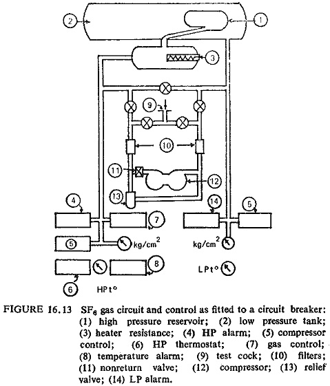
The principal components of the SF6 circuit breaker system are: a filter for removing traces of impurities by the contact of the gas with the arcs, the compressor for circulation of the gas, filter for removal of traces of oil in the gas, a relief valve for holding the valve of the high pressure within correct limits, and safety control devices for maintaining the operating pressure, for considering the mechanism inoperative when the pressure is low, where the temperatures are likely to fall below 5°C. Resistance heaters are provided in the auxiliary reservoir to maintain the gas temperature above the liquefaction point. Figure (16.13) shows the SF6 gas circuit and control as fitted to a circuit breaker.
Puffer Type Breaker:
Figure (16.14) illustrates the mode of operation of a puffer type breaker. The drawings show the contacts in the closed position, opening of the contacts with the gas being initially compressed, the instant of are extinction with the hot gases flowing through the hollow contacts, and the fully open position. Among the known Puffer type breakers this design has the following outstanding properties.
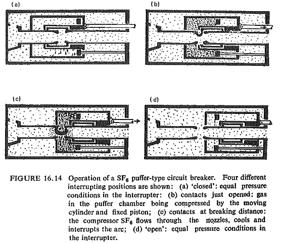
A relatively small contact clearance is used by taking full advantage of the high dielectric strength of SF6 gas. Together with short contact travel from contact separation to the extinguishing position, this results in a small arc energy, high extinguishing ability and short interrupting time. A wide clearance between the are and the insulation material, the transport of plasma and arcing products to regions with zero or low dielectric stress and a contact clearance not bridged by insulation material make use of the full dielectric properties of the SF6 gas during and after arc extinction.
Metalclad HV Switchgear:
All items of equipment including busbars, isolators, breakers, etc. are assembled in a self-contained unit. The individual elements are arranged as standardized building blocks allowing diverse combinations to be made to suit the requirements of a given installation. The complete metal enclosure is earthed to provide a safe gas-tight encasement for all line parts. The installation consists of several gas-tight compartments, SF6 pressure is kept at an average of about 4 atmospheres at 20°C. The breaker has also a high pressure section with about 14 atmospheres at 20°C for quenching the arc and operating the contacts. After every operation gas is raised to the required pressure in a closed circuit by the compressor. The operating mechanism consists of a spring and rewind motor but a hand crank is provided for emergencies. A specially designed cable-end box provides the isolation between the SF6 insulation and cable insulation. It is so designed as to permit all usual types of cables to be connected.
Recent Results and Prospects of Future Development:
Whether these techniques based on new- principles will succeed is more difficult to estimate. It is not probable that a better multiatomic gas than SF6 will be found, but perhaps a better liquid than oil is feasible. There are attractive possibilities of the combination of SF6 insulation with vacuum interrupters. Another recent suggestion is to use liquid SF6 in a container much like oil in minimum oil breakers. This may provide a solution to the problem of higher speed of operation.
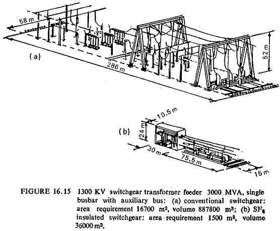
On the basis of the results obtained so far and in view of the fact that future development looks promising, a paper dealing with switchgear for a maximum operating voltage of 1300 KV has been drafted for CIGRE (Muller, 1971; Boeck and Troger, 1972).
In Fig. (16.15) a comparison is made between SF6 insulated switchgear and a conventional design for 1300 KV. SF6 insulated tubular bus systems for power transmission will moreover be used to an increasing degree.