Duties of circuit breaker diagram:
Under different circumstances Duties of circuit breaker diagram may be subjected to widely varying stresses. First of all the current varies from a few amperes due to no-load current of a transformer up to the heaviest short-circuit currents, which may amount to a hundred kilo amperes. Moreover the circuit impedance itself may change within the first 10-4 to 10-3 second because open lines or cables connected to the bus bars at the breaker behave initially like resistances (having the values of their surge impedance), but later like capacitances. Whereas load currents are more or less ohmic, short-circuit currents are purely inductive and the currents of unloaded lines are mainly capacitive.
Duties of circuit breaker diagram not only must interrupt but also must close the circuit. This may cause some trouble, especially if the breaker closes on a short circuit, because then the voltage breakdown that bridges the contact gap before the contacts touch produces a high-current arc, which melts the contacts before closure. Such a situation is not desirable since the breaker must be able to open the contacts again. Often automatic re closing is required, because usually the faults are of temporary nature. About 20% of the short circuits . persist, however, and immediately after re closing, the breaker again has to interrupt the short-circuit-current just made. This is a very severe duty, especially if there are extremely high currents requiring heavy contacts to be accelerated and decelerated in both directions within hundredths of a second without bouncing, which would result in contact welding and wear.
The main Duties of circuit breaker diagram has to perform in addition to satisfying the rated breaking capacities and rated making and breaking times are:
- Short-circuit interruption.
- Interruption of small inductive currents.
- Capacitor switching.
- Asynchronous switching.
- Interruption of short-line fault.
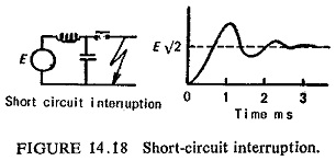
Short Circuit Interruption:
The short-circuit current depends upon the voltage E and the series reactance X. After the arc extinguishes at natural zero of the 50 Hz waveform, the circuit recovers and a restriking transient voltage or transient recovery voltage (TRV) is impressed across the switch. The magnitude and shape of the TRV waveform is very important to the circuit breaker and has already been discussed.
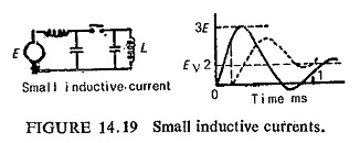
Interruption of Small Inductive Currents:
The magnetizing current of transformer is quite small, its interruption constitutes in itself no problem for a circuit breaker. The suppression of these low currents before natural zero gives rise to dangerous over voltages up to about 3.0 pu across the inductance. Some protective devices such as resistors parallel to the circuit breaker, through which the transformer energy can be discharged without causing excessive over voltages, or lightning arrestors have to be provided. Certain types of Duties of circuit breaker diagram may reignite, i.e. reestablish electrical contact, the voltage across the switch collapsing to zero. The voltage on the inductance subsequently reappears and is often smaller than voltage if no reignition had occurred (dotted curve in Fig. (14.19)).
Capacitor Switching:
Switching of unloaded transmission lines or switching of capacitor banks imposes on circuit breakers the duty of interrupting capacitive current at zero leading power factor. This can result in an abnormally high voltages across the circuit breaker gap if the breaker restrikes. It can be seen from Fig. (14.20) that at A when capacitive current zero is reached the transmission line is at maximum voltage so that when interruption occurs the line is left in a fully charged condition to this maximum value of the generated voltage. After instant A the breaker gap is subjected to the difference of voltages Vg and Vc. After a time interval of half cycle from A, i.e. at instant B the voltage across the breaker is two times maximum value of Vg. Within such a short interval of half-cycle the breaker has been subjected to a severe condition, with the result that the breaker might restrike. If such a condition occurs the voltage across the breaker falls almost instantaneously from two times maximum value of Vg to zero.
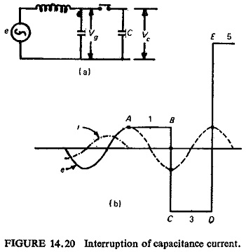
In doing so high frequency oscillations are set up which build up the voltage to —3 times maximum value of Vg. The restrike current reaches zero value which provides an opportunity to interrupt. The line is charged to a voltage of —3 times maximum value of Vg to earth after interruption of restrike current. At this stage immediately after C the voltage across the breaker is only two times maximum value of Vg since the generated voltage itself is negative maximum. The voltage across the gap now continues to increase and at D this reaches a value 4 times maximum value of Vg. If the breaker restrikes again at this point the events of B will be repeated on an even more formidable scale as the voltage swing will now be 8 times maximum Vg and the line may then be left isolated at a potential of 5 times maximum Vg to earth. Theoretically this phenomena may proceed indefinitely increasing the voltage by successive increments of 2 times maximum Vg. This is limited only by leakage and corona losses or by a breakdown of system insulation. Although these extreme conditions are improbable and rare they do sometimes occur causing serious damage. The sole cause of this type of overvoltage is the inability of the circuit breaker to provide adequate dielectric strength in the gap after interruption. Only forced-blast or multibreak HV circuit breakers can withstand this stress within such a short time.
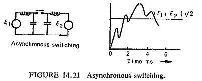
Asynchronous Switching:
Phase opposition may occur if the breaker recloses after a fairly long pause, during which the generators E1 and E2 fall out of synchronism (Fig. (14.21)). When the switch opens the peak value of the transient recovery voltage is determined by the sum of E1 and E2 and approaches two times that of the short-circuit interruption.
Interruption of Short Line Fault:
The interruption of short-circuit current due to faults on the first few km of overhead lines imposes a serious Duties of circuit breaker diagram. This is because the transient recovery voltage across the breaker terminals is accompanied by a high-frequency line-side component, whereas the reduction of short-circuit current due to the inductance of the short-circuited line is only slightly less than that of a terminal fault.
The transient voltage of the short-circuited line is proportional to the magnitude of the short-circuit current, and the frequency is inversely proportional to the length of the short-circuited line. After the interruption of the short-circuit current the voltage drop along the line is left behind in the form of a line charge. This charge decays in the form of a travelling wave oscillating at its natural frequency. The rate of rise of these oscillations is quite high owing to the effective surge impedance of the short-circuited line.
The RRRV is given by the following relation
![]()
where
I = Short circuit current
ω = service angular frequency
Z = the effective surge impedance of the short circuited line
The RRRV after interruption of a terminal short circuit is of the order of 1.5 KV/μS, whereas the interruption of a short line fault (short circuit about one km away from a line circuit breaker) can cause an RRRV of the order of 6 to 8 KV/μS, depending upon the surge impedance of the line.