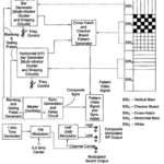
Video Test Pattern Generator
Video Test Pattern Generator: A pattern generator provides video signals directly, and with RF modulation, on standard TV channels for alignment, testing and servicing of TV receivers. The output signal…
Continue Reading
Video Test Pattern Generator