Complementary Symmetry Push Pull Amplifier
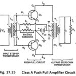
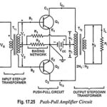
Complementary Symmetry Push Pull Amplifier: The use of transformers, at input as well as at output ends, in the push-pull amplifier shown in Fig. 17.25 makes it bulky and expensive…
Phase Splitter Circuit for Push Pull Power Amplifiers (or Phase Inverter): In a push-pull amplifier circuit an input transformer is used to provide the polarity inversion between the two input…
What is Crossover Distortion and how to eliminate it? In addition to the distortion introduced due to the nonlinearity of the collector characteristics and due to non-matching of the two…
Class B Push Pull Amplifier - Circuit Diagram, Operation and Derivation: The circuitry for the Class B Push Pull Amplifier operation is the same as that for the class A…
Class A Push Pull Amplifier - Working Principle, Advantages & Disadvantages: A Class A Push Pull Amplifier circuit is shown in Fig. 17.25. By Class A Push Pull Amplifier means…
Push Pull Amplifier - Circuit Diagram and its Workings: As we know already that, double-ended or push pull amplifiers makes use of two identical transistors in a single stage. It consists of…
Class D Power Amplifiers - Circuit Diagram, Operation and Applications: Historically, audio amplifiers have been configured as class A, class B or class AB and the art of design is…
Class B Power Amplifier - Operation and Efficiency derivation: In Class B Power Amplifier operation, the transistor is so biased that zero signal collector current is zero. Hence class B…