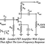
Low Frequency Response of FET Amplifier
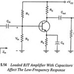
Low Frequency Response of FET Amplifier: The analysis of the Low Frequency Response of FET Amplifier is quite similar to that of the BJT amplifier. Though here common-source configuration is…
Continue Reading
Low Frequency Response of FET Amplifier