Integrated Circuit Operational Amplifier

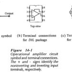
Integrated Circuit Operational Amplifier: Circuit Symbol and Packages - Figure 14-1(a) shows the triangular circuit symbol for an Integrated Circuit Operational Amplifier (op-amp). As illustrated, there are two input terminals,…

Continue Reading Integrated Circuit Operational Amplifier

Amplifier Testing

Amplifier Testing: Preparation - Transistor Amplifier Testing and other circuits should be tested in a methodical fashion; otherwise the results obtained may be useless. The circuit should first be carefully…

Continue Reading Amplifier Testing

Capacitor Coupled Common Base Amplifier

Capacitor Coupled Common Base Amplifier: A practical Capacitor Coupled Common Base Amplifier (using a plus/minus supply) is shown in Fig. 12-39. [Note the polarity of the input coupling capacitor (C1).]…

Continue Reading Capacitor Coupled Common Base Amplifier

Differential Amplifier Circuit using Transistors

Differential Amplifier Circuit using Transistors: The Differential Amplifier Circuit using Transistors is widely applied in integrated circuitry, because it has both good bias stability and good voltage gain without the…

Continue Reading Differential Amplifier Circuit using Transistors

Single Stage Common Source Amplifier

Single Stage Common Source Amplifier: Bias circuit design for the Single Stage Common Source Amplifier in shown in Fig. 12-10. As with the common-emitter BJT circuit, design commences with specification…

Continue Reading Single Stage Common Source Amplifier

Common Source Circuit Analysis

Common Source Circuit Analysis: A FET Common Source Circuit Analysis is shown in Fig. 11-­6. With the capacitors treated as ac short-circuits, the circuit input terminals are the gate and…

Continue Reading Common Source Circuit Analysis

Common Base Circuit Diagram

Common Base Circuit Diagram: The Common Base Circuit Diagram (CB) shown in Fig. 6-34 is very similar to a CE circuit, except that the input signal is applied to the…

Continue Reading Common Base Circuit Diagram