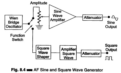
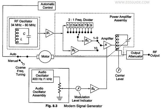
Skip to content
  • Electrical and Electronics Interview Questions and Answers
    • Electronics Engineering Interview Questions and Answers
    • Electrical Power Engineering Interview Questions and Answers
    • Communication Engineering Interview Questions and Answers
    • Digital Signal Processing Interview Questions and Answers
    • High Voltage Engineering Interview Questions and Answers
    • Total Quality Management Interview Questions and Answers
    • Environmental Engineering Interview Questions and Answers
    • Engineering Physics Interview Questions and Answers
    • Special Electrical Machines Interview Questions and Answers
    • Power System Operation and Control Interview Questions and Answers
    • Protection and Switchgear Interview Questions and Answers
    • Power Electronics Interview Questions and Answers
    • Solid State Drives Interview Questions and Answers
    • Transmission and Distribution Interview Questions and Answers
    • Microprocessor and Microcontroller Interview Questions and Answers
    • READ MORE –>
  • Viva Questions and Answers
    • Electrical Engineering viva Questions and Answers
    • Electronics Communication Engineering viva Questions and Answers
  • Multiple Choice Questions with Answers
    • Electronics Engineering Multiple Choice Questions with Answers
    • Electrical Power Engineering Multiple Choice Questions with Answers
  • Comparisons in Electrical and Electronics
    • Difference between 80186 and 80286 Microprocessor
    • Difference Between Frequency Modulation and Phase Modulation
    • Difference Between Star and Delta Connections
    • Difference Between Electric Circuit and Magnetic Circuit
    • Difference between Combinational Circuit and Sequential Circuit
    • Difference between Static RAM and Dynamic RAM
    • Difference between Linear Power Supply and SMPS
    • Difference Between Thyristor and Transistor
    • Difference Between PAM, PWM and PPM
    • Difference between Voltage Amplifier and Power Amplifier
    • Difference between Zener Breakdown and Avalanche Breakdown
    • Difference between Static Relay and Electromagnetic Relay
    • Difference between Isolator and Circuit Breaker
    • Difference between JFET and MOSFET
    • Difference between NMOS and PMOS
    • READ MORE –>
EEEGUIDE.COM
  • HOME
  • Electronics Engineering
    • Electronic Communication
    • Electronic Instrumentation
    • Electronic Devices and Circuits
    • Microprocessors and Microcontrollers
  • Electrical Power Engineering
    • Electrical Machines
    • High Voltage Engineering
    • Electric Drives
    • Fundamentals of Electrical Drives
  • Circuits and Networks
    • Integrated Circuits
    • Network Analysis and Synthesis
  • Modern Power System
    • Principles of Power System
    • Power System Protection and Switchgear
    • Power Plant Engineering
Menu Close
Search this website
  • Electronics Engineering
  • Electronic Communication
  • Electronic Instrumentation
  • Electronic Devices
  • Microprocessors and Microcontrollers
  • Electrical Power Engineering
  • Electrical Machines
  • Electrical Drives
  • High Voltage Engineering
  • Circuits and Networks
  • Integrated Circuits
  • Network Analysis and Synthesis
  • Modern Power System
  • Principles of Power System
  • Power System Protection and Switchgear
  • Power Plant Engineering
  • Interview Questions and Answers
  • Multiple Choice Questions with Answers
  • Comparisons in Electrical and Electronics
  • Viva Questions and Answers
Electronic Instrumentation / Signal Generator in Electronic Instrumentation

Color Bar Generator

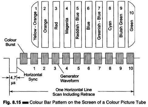
Color Bar Generator: The composite video signal at the output of a video detector consists of luminance Y signals, the chrominance signal, the color burst, sync pulses and blanking pulses. The amplitude of the video…

Comments Off on Color Bar Generator
June 17, 2017
Read more about the article Color Bar Generator
Electronic Instrumentation / Signal Generator in Electronic Instrumentation

Video Test Pattern Generator

Video Test Pattern Generator: A pattern generator provides video signals directly, and with RF modulation, on standard TV channels for alignment, testing and servicing of TV receivers. The output signal is designed to produce simple…

Comments Off on Video Test Pattern Generator
May 21, 2017
Read more about the article Video Test Pattern Generator
Electronic Instrumentation / Signal Generator in Electronic Instrumentation

Marker Generator

Marker Generator Block Diagram: Marker Generator - The sweep generator provides a visual display of the characteristics of the circuit or amplifier, but this is inadequate because it does not give any precise information of…

Comments Off on Marker Generator
May 21, 2017
Read more about the article Marker Generator
Electronic Instrumentation / Signal Generator in Electronic Instrumentation

RF Signal Generator

RF Signal Generator: An RF signal generator, when used for alignment and testing of the RF and IF stages of a TV receiver, permits recording of circuit performance at one frequency at a time. Therefore,…

Comments Off on RF Signal Generator
May 21, 2017
Read more about the article RF Signal Generator
Electronic Instrumentation / Signal Generator in Electronic Instrumentation

Block Diagram of Sweep Generator

Block Diagram of Sweep Generator: Block Diagram of Sweep Generator - It provides a sinusoidal output voltage whose frequency varies smoothly and continuously over an entire frequency band, usually at an audio rate. The process…

Comments Off on Block Diagram of Sweep Generator
May 21, 2017
Read more about the article Block Diagram of Sweep Generator
Electronic Instrumentation / Signal Generator in Electronic Instrumentation

Random Noise Generator Block Diagram and its Working

Random Noise Generator Block Diagram and its Working: A simplified Random Noise Generator Block Diagram used in the audio frequency range is shown in Fig. 8.8. The instrument offers the possibility of using a single…

Comments Off on Random Noise Generator Block Diagram and its Working
May 21, 2017
Read more about the article Random Noise Generator Block Diagram and its Working
Electronic Instrumentation / Signal Generator in Electronic Instrumentation

Pulse and Square Wave Generator Block Diagram

Pulse and Square Wave Generator Block Diagram (Laboratory Type): Pulse and Square Wave Generator are used as measuring devices in combination with a CRO. They provide both quantitative and qualitative information of the system under…

Comments Off on Pulse and Square Wave Generator Block Diagram
May 21, 2017
Read more about the article Pulse and Square Wave Generator Block Diagram
Electronic Instrumentation / Signal Generator in Electronic Instrumentation

Function Generator Block Diagram

Function Generator Block Diagram: A Function Generator Block Diagram produces different waveforms of adjustable frequency. The common output waveforms are the sine, square, triangular and sawtooth waves. The frequency may be adjusted, from a fraction…

Comments Off on Function Generator Block Diagram
May 21, 2017
Read more about the article Function Generator Block Diagram
Electronic Instrumentation / Signal Generator in Electronic Instrumentation

AF Sine and Square Wave Generator

AF Sine and Square Wave Generator: The block diagram of an AF Sine and Square Wave Generator audio oscillator is illustrated in Fig. 8.4. The signal generator is called an oscillator. A Wien bridge oscillator…

Comments Off on AF Sine and Square Wave Generator
May 21, 2017
Read more about the article AF Sine and Square Wave Generator
Electronic Instrumentation / Signal Generator in Electronic Instrumentation

Modern Laboratory Signal Generator Block Diagram and its Working

Modern Laboratory Signal Generator Block Diagram and its Working: Modern Laboratory Signal Generator - To improve the frequency stability, a single master oscillator is optimally designed for the highest frequency range and frequency dividers are…

Comments Off on Modern Laboratory Signal Generator Block Diagram and its Working
May 21, 2017
Read more about the article Modern Laboratory Signal Generator Block Diagram and its Working
  • Go to the previous page
  • 1
  • …
  • 258
  • 259
  • 260
  • 261
  • 262
  • 263
  • 264
  • …
  • 315
  • Go to the next page

Main Categories

  • Circuits and Networks
  • Electrical Machines
  • Electrical Power Engineering
  • Electronics Engineering
  • Electronic Communication Systems
  • Electronic Devices and Circuits
  • Electronic Instrumentation
  • High Voltage Engineering
  • Integrated Circuits
  • Electric Drives
  • Fundamentals of Electrical Drives
  • Microprocessors and Microcontrollers
  • Modern Power System
  • Network Analysis and Synthesis
  • Principles of Power System
  • Power System Protection and Switchgear
  • Power Plant Engineering
  • Comparisons in Electrical and Electronics
  • Electrical and Electronics Job Interview Questions and Answers
  • Multiple Choice Questions with Answers (MCQs)
  • Viva Questions and Answers

Recent Posts

  • Dual Gate MOSFET – N Channel Depletion Type MOSFET
  • Electron Orbits and Energy Levels
  • Diode Clamping Circuit – Positive and Negative Clamping
  • Hartley Oscillator using Transistor Analysis
  • Compensating Network in Op Amp
  • Single Mesh and Multi Mesh Network
  • TTL Characteristics and other TTL Series
  • Cascode Amplifier or CE-CB Configuration
  • Motion of Charged Particle in Electric Field
  • Tuned Amplifiers – Definition, Classification and Advantages
  • What is a Power Converter?
  • UJT Triggering of SCR Working Principle
  • What is Clipper Circuit? – Definition and Classification
  • Transistor Load Line Analysis (DC and AC Load Line and Q Point)
  • SCR as Half Wave Rectifier Circuit Diagram

Active users on site

  • HOME
  • PRIVACY POLICY
  • CONTACT US
  • SITEMAP
COPYRIGHT © 2014 TO 2025 EEEGUIDE.COM ALL RIGHTS RESERVED