Voltage Divider Bias Circuit

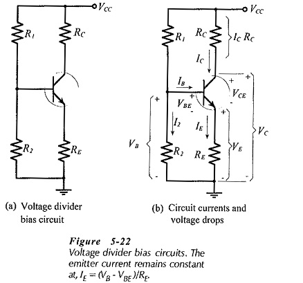
Voltage Divider Bias Circuit: Circuit Operation - Voltage Divider Bias Circuit, also known as emitter current bias, is the most stable of the three basic transistor bias circuits. A voltage divider bias circuit is shown…

Comments Off on Voltage Divider Bias Circuit

Voltage Divider Bias Circuit

Voltage Divider Bias Circuit: For the self-bias circuit, it was seen that increasing the resistance of RS brings ID(max) and ID(min) closer together, but that increased RS values result in lower ID levels. As will be demonstrated,…

Comments Off on Voltage Divider Bias Circuit

Voltage Control Method in Power System

Voltage Control Method in Power System: In a modern power system, electrical energy from the generating station is delivered to the ultimate consumers through a network of transmission and distribution. For satisfactory operation of motors,…

Comments Off on Voltage Control Method in Power System

Voltage Control by Synchronous Condenser

Voltage Control by Synchronous Condenser: The voltage at the receiving end of a transmission line can be controlled by installing specially designed synchronous motors called synchronous condensers at the receiving end of the line. The…

Comments Off on Voltage Control by Synchronous Condenser

Voltage Commutated Chopper Circuit

Voltage Commutated Chopper Circuit: This Voltage Commutated Chopper Circuit comprises an auxiliary thyristor Th2, a diode D, inductor L and capacitor C as shown in Fig. 11.32 wherein the total chopper circuitry has been outlined…

Comments Off on Voltage Commutated Chopper Circuit

Voltage Balance Differential Relay

Voltage Balance Differential Relay: In this voltage balance differential relay arrangement, two similar current transformers are connected at either end of the system element under protection (such as a feeder) by means of pilot wires.…

Comments Off on Voltage Balance Differential Relay