Gear Wheel Method for Frequency Measurement:
When a Lissajous figure contains a large number of loops, accurate counting becomes difficult. Figure 7.35 shows a test method that uses a modulated ring pattern in place of the looped figure and permits a higher count. This pattern is also called a Gear wheel or toothed wheel, because of its shape. The unknown frequency is determined by multiplying the known frequency by the number of teeth in the pattern. Figure. 7.36 shows the test set up for Gear Wheel Method for Frequency Measurement.
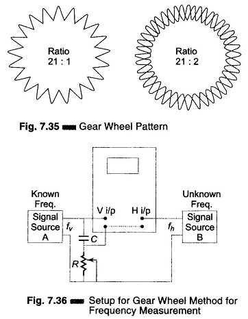
Here, a phase shift network (RC) introduces a 90° phase shift between the horizontal and vertical channels of the oscilloscope, which is needed to produce a ring or circle pattern with the known frequency fv.
A voltage from the unknown frequency source modulates this ring. When the voltages across R and C are unequal, the pattern is elliptical. If they are equal, the pattern is a circle. The unknown frequency must be higher than the known frequency and the amplitude of the unknown must be below that of the known to prevent distortion.
Set up the oscilloscope. Switch off the Internal and Sync control. Connect the circuit as in Fig. 7.36, and temporarily switch off signal B.
Switch on signal source A and adjust R to obtain a ring pattern on the screen. Adjust the horizontal and vertical gain controls to spread the ring over the screen as much as possible.
Switch on signal source B, noting that the ring becomes toothed by the signal. Adjust the known frequency fv to stop the ring from rotating. Adjust the amplitude of fh to obtain a distinct teeth pattern. The unknown frequency is then given by fh = nfv, where fh is an integral multiple (odd or even) of fv. The Gear Wheel rotates or spins if fh is not an exact multiple of fv. Therefore, adjust the known frequency to stop the Gear Wheel from rotating. This is called Gear Wheel Method for Frequency Measurement in oscilloscope.