DC Circuit Breaker:
Light duty DC Circuit Breaker have been in use since long. However, with the latest developments in HVDC transmission there would naturally be the necessity of the HVDC circuit breaker. The two major problems of HVDC circuit breaking are:
- The amount of energy to be dissipated during the short interval of breaking is very high as compared to the conventional a.c. circuit breakers.
- The natural zero current does not occur as in the case of a.c. circuit breakers.
Resistance switching and efficient cooling by forcing the liquid or air blast are used to dissipate the high amount of energy, whereas artificial means are provided to bring the current to zero.
D.C. Breaking:
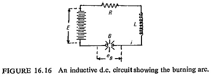
The d.c. arc extinction can be explained with the help of a circuit shown in Fig. (16.16) which is a simple d.c. circuit having a circuit breaker B assumed to break the current I = E/R. The are characteristics is shown in Fig. (16.17). It can be noted that the voltage eB across the burning arc depends on the current I flowing through the arc.
![]()
The differential equation of the circuit is
![]()
This can be written as
![]()
This can now be represented in characteristic diagram of Fig. (16.17) by plotting the resistance line. The magnitude of Δe determines the inductive voltage and thereby the rate of change of current. To the right of point ‘1’, Δe is negative, thus the current will decrease and approach point 1. To the left of point ‘1’, Δe is positive and hence this will increase the current and hence again reach point ‘1’. Hence this point represents a stable burning point of the arc.
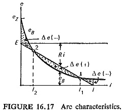
Examination of point ‘2’ shows that to the left of point ‘2’ there is steadily negative Δe which gives a steady decrease of current until zero. This therefore is the condition for the extinction of the arc. However to the right of point ‘2’ Δe is positive and the current increases and thus has no tendency of coming to point ‘2’ which unlike point ‘1’ is unstable for the maintenance of arc.
Lengthening of the are has the effect of raising the arc characteristic so that it lies above the resistance line. Progressive lengthening of arc is a basic requirement of DC Circuit Breaker. Raising of arc characteristics helps in the interruption level. Moreover the loss of energy increases with increasing length of arc and more power will be required to maintain the arc.
Light Duty D.C. Air Break Circuit Breakers:
The chief requirement of a DC Circuit Breaker is that it should interrupt the fault current in the shortest possible time. Contacts are separated at the initiation of the fault, the arc is transferred from the main contacts to the arcing contacts where the arc lengthens and then extinguishes. During this process the voltage across the arc exceeds the supply voltage. For faster actions magnetic blowouts are provided. As already explained above the idea to shift the arc characteristic above the resistance line.
General Design and Construction:
These are usually constructed as a single-pole unit suitable for mounting on a flatback switchboard of insulating material such as slate. However double-pole and three-pole breakers are possible by mechanically interlinking two or three single pole units. The single-pole breaker consists essentially of two main fixed contacts bridged by a brush with arcing contacts above it may be arranged to close either mechanically or by a solenoid, and to trip either by a series overcurrent coil, a reverse current coil, and under-voltage release, or by a relay-operated shunt release; or by combinations of these methods.
The breaker closes by means of a toggle normally, and is of the free-handle type, i.e. the breaker cannot be held closed against the action of the automatic releases; neither can it be opened slowly. The fast action is obtained by gravity or by springs.
Low current breakers up to 500 A are usually fitted with series overcurrent coils operating on a cylindrical plunger. Breakers rated above 500 A up to about 1000 A are generally fitted with an overcurrent release actuated by an iron yoke round a single-turn primary conductor, which attracts a hinged armature. For breakers exceeding 1000 A ratings overcurrent protection and reverse current protection are obtained by a shunt release coil energized by a suitable relay.
High Speed D.C. Air Break Circuit Breakers:
In order to reduce the risk of flashover on the commutators of rotating machines, or of backfire in rectifiers the time of interruption in large capacity d.c. system should be very short. The high speed of interruption automatically ensures economics in design of associated apparatus, such as rectifiers, transformers and cables.
The ordinary light duty d.c. breakers described earlier have an opening time of 0.15 to 0.4 s. An opening time of the order of 0.002 s is required for a high-speed d.c. air-break circuit breaker. In order to achieve high speed the following features are incorporated in the design.
- Light moving parts are provided.
- Only one set of breaking contacts is used because there is insufficient time in which the arcing contacts can be allowed to open after main contacts.
- Powerful springs provided for opening movement.
- Arc chute is provided for arc lengthening and extinction.
- The contacts are held closed against the action of the opening springs by an armature attracted to a shunt-excited electromagnet, and are released by the demagnetizing effect of a suitably positioned conductor (known as bucking bar), which itself carries the fault current.
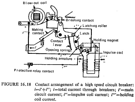
One such arrangement employing the above features is shown in Fig. (16.18). The mechanism uses two sets of contacts, for making and breaking respectively, the breaking contacts which are in series with the making contacts, close first and are, therefore, ready for a tripping operation before making contacts close. The breaker is normally tripped by deenergizing the holding magnet; for this purpose a control switch, push button, or relay may be used.
HVDC Circuit Breakers:
The greatest limitation is the difficulty in breaking large d.c. currents at high voltages. In the case of alternating current, the current passes through zero value twice every cycle. A.C. circuit breakers exploit this property to interrupt the current and the problem for the circuit breaker reduces to prevention of restriking after a current zero. DC Circuit Breaker do not have this natural advantage and therefore have to force the current to zero from the short-circuit value by some means. In addition to this another problem with DC Circuit Breaker is the dissipation of large amount of electromagnetic energy stored in the circuit.
In designing an HVDC circuit breaker there are three main problems to be solved:
- How to produce a current zero?
- How to prevent restriking?
- How to dissipate the stored energy?
Each of these problems will be discussed in turn.
(a) Producing Current Zero: A fundamental problem in the design of DC Circuit Breaker is the production of current zero artificially. This approach involves changing the form of arc current by commutation principle and using the quenching gear of the well proven HVAC circuit breakers for arc clearance.
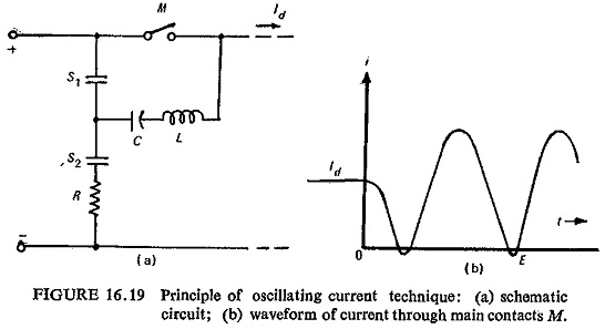
One such scheme is based on the principle of oscillatory circuit shown in Fig. (16.19). A series resonant circuit with L and C connected across the main contacts M of a conventional a.c. circuit breaker through an auxiliary contact S1. Resistance it is connected through contacts S2. Under normal conditions M and S2 are closed thus C is charged to line voltage, contacts S1 are open and have line voltage across them. In order to interrupt the d.c. current the contacts S2 are opened and S1 is closed, thus discharging the capacitor C through L, M and S1 which sets up an oscillatory current shown in Fig. (16.19b). This creates artificial current zeros and the circuit breaker M can be opened. Thereafter contacts S1 are opened and S2 are closed.
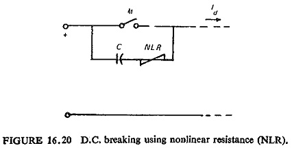
Another method is to divert the main current to the capacitor with the result that the current to be interrupted by M is small. This is illustrated in Fig. (16.20). The rate of rise of recovery voltage across M is dVc/dt = Id/C. The nonlinear resistor absorbs energy without greatly adding to the voltage across M.
(b) Prevention of Restrikes: This problem is more acute in oscillating current DC Circuit Breaker, where the time in which the current is chopped is very small (of the order of 100 μa). This causes a steep surge of restriking voltage across the terminals. The circuit breaker must be able to withstand this voltage.
To produce a good deionizing arc the space between two walls of arc chute can be narrowed to restrict the arc and at the same time it can be broken into a number of smaller arcs by inserting a grating of vertical metal plates.
(c) Dissipation of Stored Energy: A large amount of energy stored in the circuit inductance at the beginning of the interruption plus that supplied by the rectifier during the time of interruption has to be dissipated by some If it is not, it will transfer to the system capacitance and create overvoltages. The method used to dissipate this energy determines to a large extent the cost of .the scheme. A protective spark gap can be used across the circuit breaker to reduce the size of commutating capacitor. Further, it will keep the abnormal voltage produced at the switching time below undesired levels. By means of high frequency currents the spark gap acts as an energy dissipating device.
HVDC Vacuum Circuit Breaker:
The effectiveness of the commutation principle, has been demonstrated by using vacuum interrupters as a means for interrupting high direct current at high voltage. Currents in excess of 15 KA at 20 KV have been interrupted by a single device in an inductive circuit.
Because of the fact that extremely fast interruption is required for d.c. breakers, the vacuum interrupter constitutes an ideal device for a circuit breaker where extremely rapid response is required. In the first instance, the critical contact separation to achieve interruption is quite small (of the order of 5 to 10 mm). Moreover, the inertia mass of the moving system is relatively low, essentially comprising only the contacts. Ultra high speed for the mechanism can be achieved by means of a high-pressure hydraulic system.
As the arc plasma diffuses in vacuum at a very rapid rate so the vacuum interrupters are ideal, because otherwise the interruption will become difficult because of the plasma in the contact gas when the recovery voltage is rising.
Experimental HVDC vacuum circuit breakers have been built and tested.