CW Doppler Radar Block Diagram:
A simple CW Doppler Radar Block Diagram, such as the one shown in Figure 16-14, sends out continuous sine waves rather than pulses. It uses the Doppler effect to detect the frequency change caused by a moving target and displays this as a relative velocity.
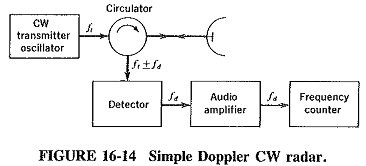
Since transmission here is continuous, the circulator of CW Doppler Radar Block Diagram in Figure 16-14 is used to provide isolation between the transmitter and the receiver. Since transmission is continuous, it would be pointless to use a duplexer. The isolation of a typical circulator is of the order of 30 dB, so that some of the transmitted signal leaks into the receiver. The signal can be mixed in the detector with returns from the target, and the difference is the Doppler frequency. Being generally in the audio range in most Doppler applications, the detector output can be amplified with an audio amplifier before being applied to a frequency counter. The counter is a normal one, except that its output is shown as kilometres or miles per hour, rather than the actual frequency in hertz. The main disadvantage of a system as simple as this is its lack of sensitivity. The type of diode detector that is used to accommodate the high incoming frequency is not a very good device at the audio output frequency, because of the modulation noise which it exhibits at low frequencies. The receiver whose block diagram is shown in Figure 16-15 is an improvement in that regard.
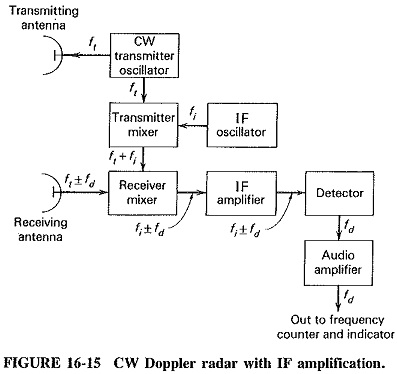
A small portion of the transmitter output is mixed with the output at a local oscillator, and the sum is fed to the receiver mixer. This also receives the Doppler-shifted signal from its antenna and produces an output difference frequency that is typically 30 MHz, plus or minus the Doppler Frequency. The output of this mixer is amplified and demodulated again, and the signal from the second detector is just the Doppler frequency. Its sign is lost, so that it is not possible to tell whether the target is approaching or receding. The overall receiver system is rather similar to the superheterodyne. Extra sensitivity is provided by the lowered noise, because the output of the diode mixer is now in the vicinity of 30 MHz, at which FM noise has disappeared.
Separate receiving and transmitting antennas have been shown, although this arrangement is not compulsory. A circulator could be used, as in the simpler set of Figure 16-14. Separate antennas are used to increase the isolation between the transmitter and receiver sections of the radar, especially since there is no longer any need for a small portion of the transmitter output to leak into the receiver mixer, as there was in the simpler set. To the contrary, such leakage is highly undesirable, because it brings with it the hum and noise from the transmitter and thus degrades the receiver performance. The problem of isolation is the main determining factor, rather than any other single consideration in the limiting of the transmitter output power. As a consequence, the CW power from such a radar seldom exceeds 100 W and is often very much less. Gunn or IMPATT diodes or, for the highest powers, CW magnetrons are used as power oscillators in the transmitter. They operate at much the same frequencies as in pulsed radar.
Advantages, Applications and Limitations:
CW Doppler Radar Block Diagram radar is Capable of giving accurate measurements of relative velocities, using low transmitting powers, simple circuitry, low power consumption and equipment whose size is much smaller than that of comparable pulsed equipment. It is unaffected by the presence of stationary targets, which it disregards in much the same manner as MTI pulsed radar (it also has blind speeds, for the same reason as MTI). It can operate (theoretically) down to zero range because, unlike in the pulsed system, the receiver is. ON at all times. It is also capable of measuring a large range of target speeds quickly and accurately. With some additional circuitry. CW radar can even measure the direction of the target, in addition to its speed.
Before the reader begins to wonder why pulsed radar is still used in the majority of equipment, it must be pointed out that CW Doppler radar has some disadvantages also. In the first place, it is limited in the maximum power it transmits, and this naturally places a limit on its maximum range. Second, it is rather easily confused by the presence of a large number of targets (although it is capable of dealing with more than one if special filters are included). Finally (and this is its greatest drawback), Doppler radar is incapable of indicating the range of the target. It can only show its velocity, because the transmitted signal is unmodulated. The receiver cannot sense which particular cycle of oscillations is being received at the moment, and therefore cannot tell how long ago this particular cycle was transmitted, so that range cannot be measured.
As a result of its characteristics and despite its limitations, the CW Doppler Radar Block Diagram system has quite a number of applications. One of these is in aircraft navigation for speed measurement. Another application is in a rate-of-climb meter for vertical-takeoff planes, such as the “Harrier,” which in 1969 became the first jet ever to land on Manhattan Island, in New York City. Finally, perhaps its most commonly encountered application is in the radar speed meters used by police.