Current and Voltage Connection in Distance Relay:
It is essential for the distance relay to measure the same distance between the fault and the relay under any type of fault condition. It is possible to supply the relays so that they will always measure Z1 the positive sequence impedance of the protected feeder, by suitable choice of Current and Voltage Connection in Distance Relay, under any fault condition. It is usual to employ three phase fault measuring relays and three earth fault measuring relays—one for each phase-pair and phase respectively.
(i) Connections for Phase Fault Relays: In the case of phase faults comprising three-phase, phase-to-phase and double-phase-to-earth faults, this is achieved by supplying the relay with voltage across the faulty phases and the vector difference of the currents in the two faulty phases, i.e.
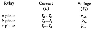
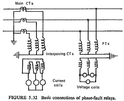
With these signals the relay measures Z1 of the line section up to the fault location for any of the type of phase faults. Basic connections of phase-fault relays are shown in Fig. (5.32).
Sequence network connections are shown for different types of phase faults in Fig. (5.33). For a given phase-pair, say b-c, positive and negative sequence voltages at fault Vf1 and Vf2 are equal.
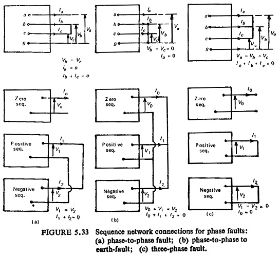
Similarly for a three-phase fault also the positive and negative sequence voltages at fault are zero and hence again are equal. At relay location the positive and negative sequence voltages are:
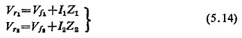
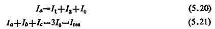
where I1 and I2 are sequence currents and Z1, Z2 the sequence impedances of the line. Since Z1 = Z2 for lines and Vf1 = Vf2, we have
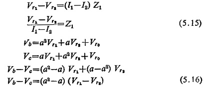
Similarly
![]()
Hence
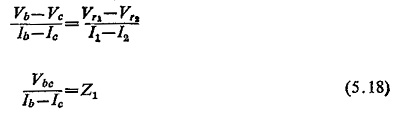
This shows that for any type of phase faults the impedance seen by the relay will be the positive sequence impedance of the line up to the fault point.
(ii) Connections for Earth-Fault Relays: Under earth-fault conditions the impedance measured by the relay would be equal to Ze the earth loop impedance if the relay was supplied with phase-neutral volts and phase neutral current on a system earthed at one point only behind the relay location. However, on a system earthed at more than one point the measured impedance would vary depending upon the position and number of earth points. In order that the relays again measure the same impedance Z1 under earth-fault conditions on a general system, it is necessary to add to the phase-neutral current a proportion of the residual current at the relay point. This is known as residual compensation and is achieved in practice by means of a tapped auto-transformer in the residual circuit of the main CT as shown in Fig. (5.34).

The voltage drop to the fault is the sum of the sequence voltage drops between the relaying point and the fault, viz. for fault on phase a in reference to Fig. (5.35).
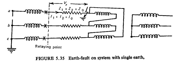
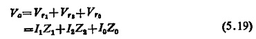
Also
where Ires is the residual current and Ia, Ib, Ic are the phase currents at relaying point.
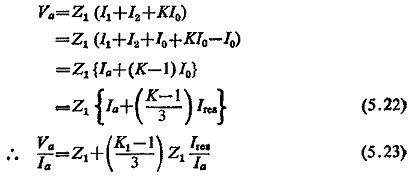
In order to make this equal to Z1 the second factor in Eq. (5.23) has to be eliminated which is done by adding (K-I) Ires/3 to the phase current.
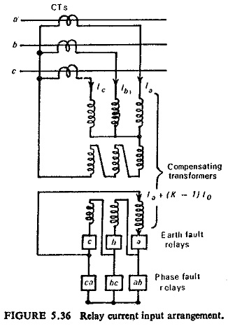
The combined relay current input arrangement for phase and earth faults can thus be represented as in Fig. (5.36).