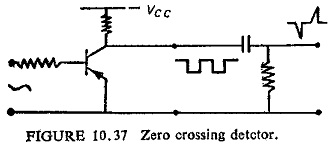
Zero Crossing Detector Circuit
Zero Crossing Detector Circuit: Zero Crossing Detector Circuit basically involves the sine to square wave conversion by a level detector circuit followed by a pulse circuit, which consists of one shot monostable circuit or a…
Comments Off on Zero Crossing Detector Circuit
June 27, 2019