Induction Motor Drives

Working Principle of Linear Induction Motor

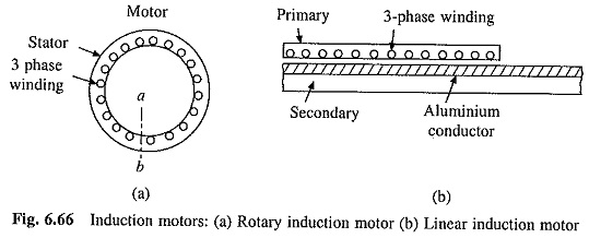
Working Principle of Linear Induction Motor: While the conventional induction motor gives rotary motion, a Working Principle of Linear Induction Motor provides translational or linear motion. Hence it is termed linear induction motor. To understand the principle of operation let us examine stator of the rotary induction motor (Fig. 6.66(a)). Let the stator be cut …

Working Principle of Linear Induction Motor Read More »

Single Phase Induction Motors Working Principle

Single Phase Induction Motors Working Principle: Single Phase Induction Motors Working Principle are inferior in performance and lager in weight and volume compared to three-phase motors of the same rating. However, they are simple, robust, reliable and less expensive for small ratings. They are employed in low power drives in small industries and domestic and …

Single Phase Induction Motors Working Principle Read More »

Variable Speed Constant Frequency Generator

Variable Speed Constant Frequency Generator: Variable Speed Constant Frequency Generator (VSCF) involves generation of electrical power at fixed frequency and fixed voltage from a variable speed prime mover coupled to the generator shaft. Wind generator is one such example. Speed of rotor varies with velocity and pressure of the wind, but power delivered to the …

Variable Speed Constant Frequency Generator Read More »

Slip Power Recovery Scheme used in Induction Motor

Slip Power Recovery Scheme used in Induction Motor: Slip Power Recovery Scheme used in Induction Motor – Figure 6.53 shows an equivalent circuit of a wound-rotor induction motor with voltage Vr injected into its rotor, assuming stator-to-rotor turns ratio unity. When rotor copper loss is neglected where Pr is the power absorbed by the source …

Slip Power Recovery Scheme used in Induction Motor Read More »

Rotor Resistance Control of Induction Motor

Rotor Resistance Control of Induction Motor: Speed-torque curves for Rotor Resistance Control of Induction Motor are given in Fig. 6.50. While maximum torque is independent of rotor resistance, speed at which the maximum torque is produced changes with rotor resistance. For the same torque, speed falls with an increase in Rotor Resistance Control of Induction …

Rotor Resistance Control of Induction Motor Read More »

Current Regulated Voltage Source Inverter

Current Regulated Voltage Source Inverter: Current Regulated Voltage Source Inverter operates with current controlled PWM. In current controlled pulse-width modulation, machine phase current is made to follow a sinusoidal reference current within a hysteresis band. Fig. 6.48(a) shows a sinusoidal reference current i*A = Im sin ωt. Two bands, separated from i*A by an amount Δl, are shown in …

Current Regulated Voltage Source Inverter Read More »

Current Source Inverter Control of Induction Motor

Current Source Inverter Control of Induction Motor: A thyristor Current Source Inverter Control of Induction Motor (CSI) is shown in Fig. 6.45. Diodes D1-D6 and capacitors C1-C6 provide commutation of thyristors T1-T6, which are fired with a phase difference of 60° in sequence of their numbers. It also shows the nature of output current waveforms. Inverter …

Current Source Inverter Control of Induction Motor Read More »

Scroll to Top