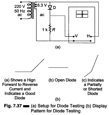
Oscilloscope

Digital Readout Oscilloscope

Digital Readout Oscilloscope: The Digital Readout Oscilloscope instrument has a CRT display and a counter display. The diagram shown is of an instrument where the counter measures the time (Fig. 7.29). The input waveform is sampled and the sampling circuit advances the sam­pling position in fixed increments, a process called strobing. The equivalent time between

Digital Readout Oscilloscope Read More »

Storage Oscilloscope

Storage Oscilloscope (For VLF Signal): Storage Oscilloscope – Storage targets can be distinguished from standard phosphor targets by their ability to retain a waveform pattern for a long time, independent of phosphor peristence. Two storage techniques are used in oscilloscope CRTs, mesh stor­age and phosphor storage. A mesh-Storage Oscilloscope uses a dielectric material deposited on

Storage Oscilloscope Read More »

What is Sampling Oscilloscope?

What is Sampling Oscilloscope?: An ordinary Sampling Oscilloscope has a B.W. of 10 MHz. The HF performance can be improved by means of sampling the input waveform and reconstructing its shape from the sample, i.e. the signal to be observed is sampled and after a few cycles the sampling point is advanced and another sample

What is Sampling Oscilloscope? Read More »

Dual Trace Oscilloscope

Dual Trace Oscilloscope: Figure 7.19 (a) shows a block diagram of Dual Trace Oscilloscope. This CRO has a single electron gun whose electron beam is split into two by an electronic switch. There is one control for focus and another for intensity. Two signals are displayed simultaneously. The signals pass through identical vertical channels or

Dual Trace Oscilloscope Read More »

Scroll to Top