Skip to content
  • Electrical and Electronics Interview Questions and Answers
    • Electronics Engineering Interview Questions and Answers
    • Electrical Power Engineering Interview Questions and Answers
    • Communication Engineering Interview Questions and Answers
    • Digital Signal Processing Interview Questions and Answers
    • High Voltage Engineering Interview Questions and Answers
    • Total Quality Management Interview Questions and Answers
    • Environmental Engineering Interview Questions and Answers
    • Engineering Physics Interview Questions and Answers
    • Special Electrical Machines Interview Questions and Answers
    • Power System Operation and Control Interview Questions and Answers
    • Protection and Switchgear Interview Questions and Answers
    • Power Electronics Interview Questions and Answers
    • Solid State Drives Interview Questions and Answers
    • Transmission and Distribution Interview Questions and Answers
    • Microprocessor and Microcontroller Interview Questions and Answers
    • READ MORE –>
  • Viva Questions and Answers
    • Electrical Engineering viva Questions and Answers
    • Electronics Communication Engineering viva Questions and Answers
  • Multiple Choice Questions with Answers
    • Electronics Engineering Multiple Choice Questions with Answers
    • Electrical Power Engineering Multiple Choice Questions with Answers
  • Comparisons in Electrical and Electronics
    • Difference between 80186 and 80286 Microprocessor
    • Difference Between Frequency Modulation and Phase Modulation
    • Difference Between Star and Delta Connections
    • Difference Between Electric Circuit and Magnetic Circuit
    • Difference between Combinational Circuit and Sequential Circuit
    • Difference between Static RAM and Dynamic RAM
    • Difference between Linear Power Supply and SMPS
    • Difference Between Thyristor and Transistor
    • Difference Between PAM, PWM and PPM
    • Difference between Voltage Amplifier and Power Amplifier
    • Difference between Zener Breakdown and Avalanche Breakdown
    • Difference between Static Relay and Electromagnetic Relay
    • Difference between Isolator and Circuit Breaker
    • Difference between JFET and MOSFET
    • Difference between NMOS and PMOS
    • READ MORE –>
EEEGUIDE.COM
  • HOME
  • Electronics Engineering
    • Electronic Communication
    • Electronic Instrumentation
    • Electronic Devices and Circuits
    • Microprocessors and Microcontrollers
  • Electrical Power Engineering
    • Electrical Machines
    • High Voltage Engineering
    • Electric Drives
    • Fundamentals of Electrical Drives
  • Circuits and Networks
    • Integrated Circuits
    • Network Analysis and Synthesis
  • Modern Power System
    • Principles of Power System
    • Power System Protection and Switchgear
    • Power Plant Engineering
Menu Close
  • Electronics Engineering
  • Electronic Communication
  • Electronic Instrumentation
  • Electronic Devices
  • Microprocessors and Microcontrollers
  • Electrical Power Engineering
  • Electrical Machines
  • Electrical Drives
  • High Voltage Engineering
  • Circuits and Networks
  • Integrated Circuits
  • Network Analysis and Synthesis
  • Modern Power System
  • Principles of Power System
  • Power System Protection and Switchgear
  • Power Plant Engineering
  • Interview Questions and Answers
  • Multiple Choice Questions with Answers
  • Comparisons in Electrical and Electronics
  • Viva Questions and Answers
Electronic Devices and Circuits / IC Operational Amplifiers

Instrumentation Amplifier Circuit Working

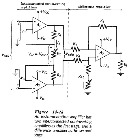
Instrumentation Amplifier Circuit Working: Circuit Operation - At first glance, the Instrumentation Amplifier Circuit Working in Fig. 14-28 looks complex, but when considered section by section it is found to be quite simple. First, note…

Comments Off on Instrumentation Amplifier Circuit Working
February 27, 2019
Read more about the article Instrumentation Amplifier Circuit Working
Electronic Devices and Circuits / IC Operational Amplifiers

Differential Amplifier Circuit Operation

Differential Amplifier Circuit Operation: A Differential Amplifier Circuit Operation amplifies the difference between two inputs. The circuit shown in Fig. 14-23 is a combination of inverting and noninverting amplifiers. Resistors R1, R2, and the op-amp…

Comments Off on Differential Amplifier Circuit Operation
February 27, 2019
Read more about the article Differential Amplifier Circuit Operation
Electronic Devices and Circuits / IC Operational Amplifiers

Direct Coupled Inverting Amplifier

Direct Coupled Inverting Amplifier: The circuit in Fig. 14-18 is termed an Direct Coupled Inverting Amplifier because, with Vi applied via R1 to the inverting input terminal, the output goes negative when the input goes positive, and…

Comments Off on Direct Coupled Inverting Amplifier
February 27, 2019
Read more about the article Direct Coupled Inverting Amplifier
Electronic Devices and Circuits / IC Operational Amplifiers

Non Inverting Amplifier Theory

Non Inverting Amplifier Theory: Direct-Coupled Noninverting Amplifier - The Non Inverting Amplifier Theory circuit in Fig. 14-14 behaves similarly to a voltage follower circuit with one major difference. Instead of all of the output voltage…

Comments Off on Non Inverting Amplifier Theory
February 27, 2019
Read more about the article Non Inverting Amplifier Theory
Electronic Devices and Circuits / IC Operational Amplifiers

Voltage Follower Circuit Diagram

Voltage Follower Circuit Diagram: Direct-Coupled Voltage Follower - The IC operational amplifier can be employed for an infinite variety of applications. The very simplest application is the direct-coupled Voltage Follower Circuit Diagram shown in Fig:…

Comments Off on Voltage Follower Circuit Diagram
February 27, 2019
Read more about the article Voltage Follower Circuit Diagram
Electronic Devices and Circuits / IC Operational Amplifiers

Biasing Bipolar Op Amp Circuit

Biasing Bipolar Op Amp Circuit: Biasing Bipolar Op Amp Circuit - Like other electronic devices, operational amplifiers must be correctly biased if they are to function properly. As already discussed, the inputs of an operational…

Comments Off on Biasing Bipolar Op Amp Circuit
February 27, 2019
Read more about the article Biasing Bipolar Op Amp Circuit
Electronic Devices and Circuits / IC Operational Amplifiers

Integrated Circuit Operational Amplifier

Integrated Circuit Operational Amplifier: Circuit Symbol and Packages - Figure 14-1(a) shows the triangular circuit symbol for an Integrated Circuit Operational Amplifier (op-amp). As illustrated, there are two input terminals, one output terminal, and two…

Comments Off on Integrated Circuit Operational Amplifier
February 27, 2019
Read more about the article Integrated Circuit Operational Amplifier
Amplifiers with Negative Feedback / Electronic Devices and Circuits

Effects of Negative Feedback in Amplifiers

Effects of Negative Feedback in Amplifiers: Decibels of Feedback - Effects of Negative Feedback in Amplifiers can be measured in decibels. A statement that 40 dB of feedback has been applied to an amplifier means…

Comments Off on Effects of Negative Feedback in Amplifiers
February 27, 2019
Read more about the article Effects of Negative Feedback in Amplifiers
Amplifiers with Negative Feedback / Electronic Devices and Circuits

Parallel Current Negative Feedback Circuit

Parallel Current Negative Feedback Circuit: Current Feedback Circuit - In series-voltage feedback, a portion of the output voltage is fed back in series with the signal source. In Parallel Current Negative Feedback Circuit, a portion…

Comments Off on Parallel Current Negative Feedback Circuit
February 27, 2019
Read more about the article Parallel Current Negative Feedback Circuit
Amplifiers with Negative Feedback / Electronic Devices and Circuits

Emitter Current Feedback Circuit

Emitter Current Feedback Circuit: Emitter Current Feedback Circuit is produced by connecting an unbypassed resistor in series with the emitter terminal of a transistor, as shown in Fig. 13-24(a). The effects of an unbypassed emitter…

Comments Off on Emitter Current Feedback Circuit
February 26, 2019
Read more about the article Emitter Current Feedback Circuit
  • Go to the previous page
  • 1
  • …
  • 4
  • 5
  • 6
  • 7
  • 8
  • 9
  • 10
  • …
  • 18
  • Go to the next page

Main Categories

  • Circuits and Networks
  • Electrical Machines
  • Electrical Power Engineering
  • Electronics Engineering
  • Electronic Communication Systems
  • Electronic Devices and Circuits
  • Electronic Instrumentation
  • High Voltage Engineering
  • Integrated Circuits
  • Electric Drives
  • Fundamentals of Electrical Drives
  • Microprocessors and Microcontrollers
  • Modern Power System
  • Network Analysis and Synthesis
  • Principles of Power System
  • Power System Protection and Switchgear
  • Power Plant Engineering
  • Comparisons in Electrical and Electronics
  • Electrical and Electronics Job Interview Questions and Answers
  • Multiple Choice Questions with Answers (MCQs)
  • Viva Questions and Answers

Recent Posts

  • Design of Electrical Apparatus Interview Questions and Answers
  • Power Electronics Interview Questions and Answers
  • Transmission and Distribution Interview Questions and Answers
  • Microprocessor and Microcontroller Interview Questions and Answers
  • Difference between I/O Mapped I/O and Memory Mapped I/O
  • High Voltage Engineering Interview Questions and Answers
  • Power System Control Interview Questions and Answers
  • Solid State Drives Interview Questions and Answers
  • Principles of Management Interview Questions and Answers
  • Operating System Interview Questions and Answers

Active users on site

  • HOME
  • PRIVACY POLICY
  • CONTACT US
  • SITEMAP
COPYRIGHT © 2014 TO 2025 EEEGUIDE.COM ALL RIGHTS RESERVED