Attenuator Network:
An attenuator network must fulfil following conditions.
- It must give correct input impedance,
- It must give correct output impedance and
- It must provide specified attenuation.
In general, attenuation is expressed in decibel as follows,
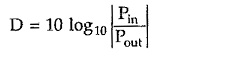
where D is the attenuation in decibel.
But we can express attenuation in neper as follows,
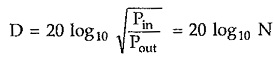
where N is the attenuation in neper.
![]()
In this topic, we shall study symmetrical attenuators such as symmetrical T type, symmetrical π type, lattice type and bridged T type, alongwith asymmetrical attenuator such as ‘L’ type attenuator.
Any Attenuator Network is designed for specified characteristic resistance R0 and attenuation.
Let us find design equations for various Attenuator Network one by one.
Symmetrical T Type Attenuator:
Consider properly terminated symmetrical T network as shown in the Fig. 10.3.
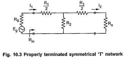
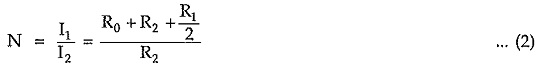
According to current divider rule,
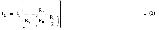
But for symmetrical networks,
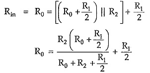
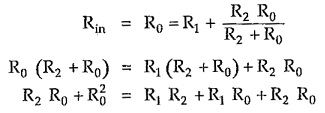
For properly terminated network, input impedance Rin is given by,
From equation (2),
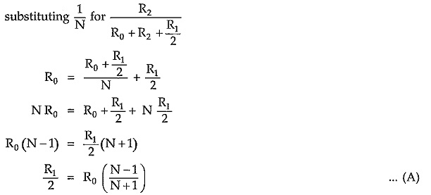
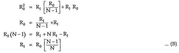
From equation (2), we can write,
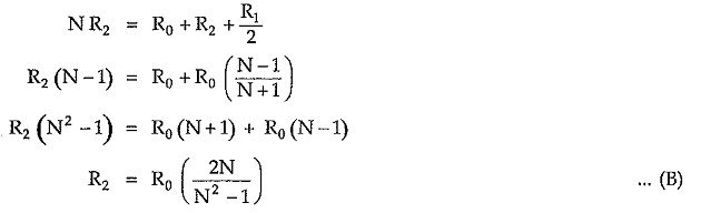
Equations (A) and (B) are called design equations of symmetrical T attenuator.
Symmetrical π Type Attenuator:
Consider properly terminated symmetrical π network as shown in the Fig. 10.5.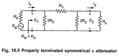 Let the characteristic impedance be pure resistive i.e. R0 and propagation constant γ = α. Then according to the theory of symmetrical network, the shunt arm and series arm can be expressed interms of R0 and α as follows,
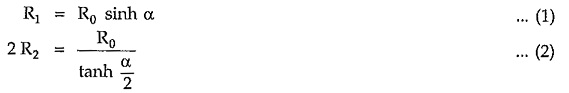 Simplifying equation (1),
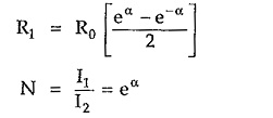
Simplifying equation (2),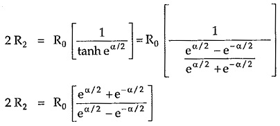
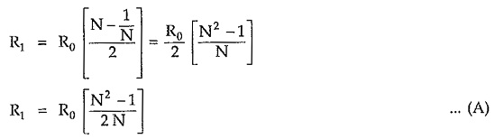
Multiplying numerator and denominator by factor eα/2 on right handside of the equation,
Equations (A) and (B) are called design equations of symmetrical π attenuator.
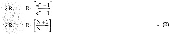
Symmetrical Lattice Type Attenuator:
Consider properly terminated lattice Attenuator Network as shown in the Fig. 10.7 (a).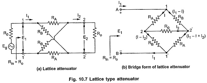
According to the theory of the symmetrical networks, characteristic impedance is the geometric mean of open and short circuit impedance.
Consider lattice network shown in the Fig. 10.8 (a) and (b) with open and short circuit output terminals respectively.
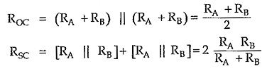
By definition, characteristic impedance is given by,
![]()
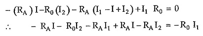
Consider Fig. 10.7, applying KVL to closed path A-1-2-2′-1′-2-A, we can write,
![]()
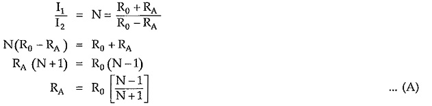
Thus, we can write,
Applying KVL to closed path A-1-2′-2–1′-B-A, we can write,
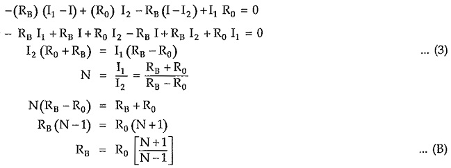
Equations (A) and (B) are called design equations of symmetrical lattice attenuator.
Bridged T Attenuator:
Consider properly terminated bridged T network as shown in the Fig. 10.10. Assuming 3 loop currents in clockwise direction as shown.
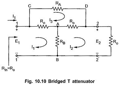
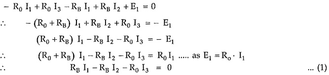
Consider closed path 1-A-B-1′-1, applying KVL,
Consider closed path A-2-2′-B-A, applying KVL,

Consider closed path C-D-2-A-1-C, applying KVL,

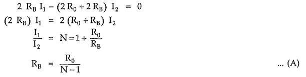
Adding equations (1) and (2),
From equation (1) we can write,
![]()
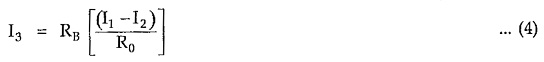
Substituting value of I3 in
Substituting value of RB from equation (A) we can write,
Equations (A) and (B) are called design equations of bridged T attenuator.
L Type Asymmetrical Attenuator:
An asymmetrical L type attenuator is as shown in the Fig. 10.12.
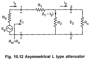
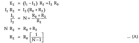
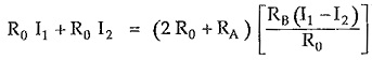
Input resistance looking into network from terminals 1-1′ is
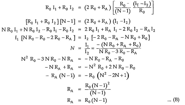
Putting value of R2 from equation (A),
equations (A) and (B) are called design equations of asymmetrical L type attenuator.