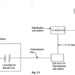
Single Line Diagram of Electrical System
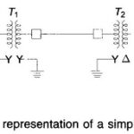
Single Line Diagram of Electrical System: The function of an Structure of Electrical Power System is to connect the power station to the consumers' loads by means of interconnected system…
Continue Reading
Single Line Diagram of Electrical System