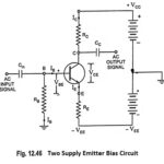
Two Supply Emitter Bias Circuit
Two Supply Emitter Bias Circuit: From the stability point of view, this two supply emitter bias circuit is the best of all already discussed circuits, but it has one drawback…
Continue Reading
Two Supply Emitter Bias Circuit