Basic Controls of CRO:
Number of controls are required to be provided on a panel of CRO to facilitate its proper functioning. Intensity control is provided for adjustment of brightness of the spot on the screen. It is accomplished by varying the voltage between the first and second anodes. The horizontal and vertical position controls are provided for moving the beam on any part of the screen. It is accomplished by applying a dc voltage to horizontal or vertical deflection plates. Similarly there are other numerous Basic Controls of CRO, which will be discussed, in detail, here.
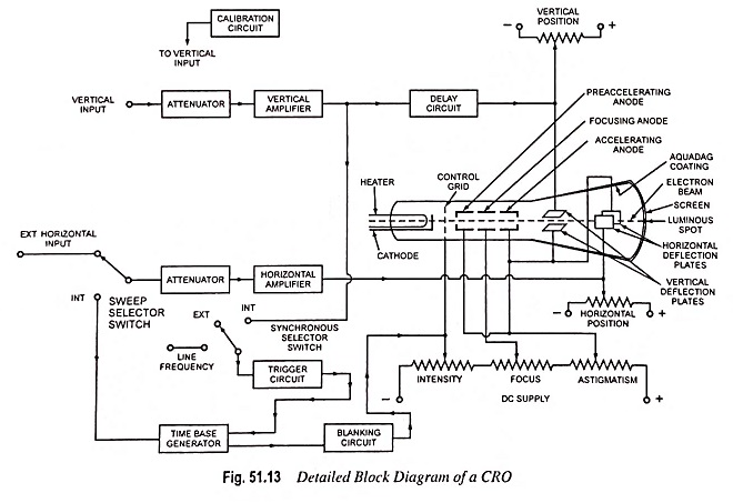
A block diagram of a basic CRO is shown in Fig. 51.13.
1. Vertical Deflection System: The function of vertical deflection system is to provide an amplified signal of the proper level to drive the vertical deflection plates without introducing any appreciable distortion into the system.
The input sensitivity of many CROs is of the order of a few millivolts per division and the voltage required for deflecting the electron beam varies from approximately 100 V (peak to peak) to 500 V depending on the accelerating voltage and the construction of the tube. Thus the vertical amplifier is required to provide this desired gain from millivolt input to several hundred volt (peak-to-peak) output. Also the vertical amplifier should not distort the input waveform and should have good response for entire band of frequencies to be measured.
The deflection plates of CRO act as plates of a capacitor and when the input signal frequency exceeds over 1 MHz, the current required for charging and discharging of the capacitor formed by the deflection plates increases. So the vertical amplifier should be capable of supplying current enough to charge and discharge the deflection plate capacitor.
As we know that electrical signal is delayed by a certain amount of time when transmitted through an electronic circuitry. In CRO, output signal voltage of the vertical amplifier is fed to the vertical plates of CRT and some of its portion is used for triggering the time base generator circuit, whose output is supplied to the horizontal deflection plates through horizontal amplifier. The whole process, which includes generating and shaping of a trigger pulse and starting of a time base generator and then its amplification, takes time of the order of 100 ns or so. So the input signal of the vertical deflection plates of a CRT is to be delayed by at least the same or little more amount of time to allow the operator to see the leading edge of the signal waveform under study on the screen. For this purpose, delay line circuit is introduced between vertical amplifier and the plates of CRT, as shown in Fig. 51.13.
2. Horizontal Deflection System: External signal is applied to horizontal deflection plates through the horizontal amplifier at the sweep selector switch in EXT position, as shown in Fig. 51.13. The horizontal amplifier, similar to the vertical amplifier, increases the amplitude of the input signal to the level required by the horizontal deflection plates of CRT.
When the function of time is required to be displayed on the screen of CRT, INT position of sweep selector switch is used. Before going further we should make ourselves clear first about the linear time base pattern.
Assume that we supply an ideal sawtooth signal voltage to the horizontal deflection plates, keeping vertical deflection plates at zero potential, as shown in Fig. 51.14.
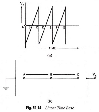
At the starting point A in time, signal voltage is maximum but negative so the spot on the screen of CRO is at the extreme left position. Further at point B in time, signal voltage applied to the horizontal plates is zero so the spot is in the centre position on the screen. Now when voltage increases in + ve direction and becomes maximum just before the point C, the spot on the screen is at the extreme right side of the screen. Just after the point C, next cycle of sawtooth voltage signal starts and again voltage becomes maximum negative so the spot goes back to the extreme left position of the screen from right position in no time.
From the above discussion we may conclude that
- The spot moves from left to right over the same path again for every cycle of sawtooth voltage applied to the horizontal deflection plates, so a horizontal line appears on the screen of CRO.
- The spot moves from left to right on the screen with the uniform speed. Thus it produces a linear time base to display function of time on the screen of CRO.
For making idea of time base more clear let us discuss an application. Suppose a sinusoidal voltage signal Vv of time period T is applied to the vertical deflection plates and a sawtooth voltage signal Vh of time period T is applied to horizontal deflection plates, as shown in Fig. 51.15.
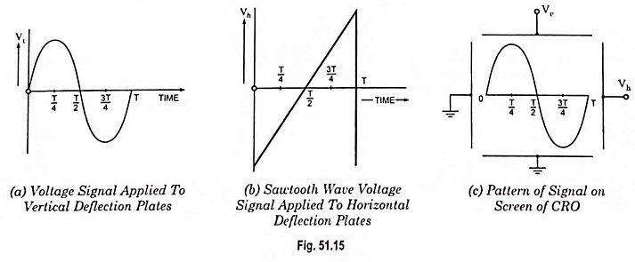
At zero time, the spot is at extreme left vertically central position on the screen because of zero value of Vv and maximum negative value of Vh. At time T/4, the spot is at one-fourth way on the screen in horizontal direction and at maximum positive
deflection above the centre line in vertical direction because of maximum positive value of Vv. At time T/2, values of both Vv and Vh are zero, so the spot is at the central position of the screen.
At time 3T/4, the spot is the three-fourth way on the screen in horizontal direction and at the maximum negative deflection in vertical direction. Finally, at the end of time T, the spot is at extreme right vertically central position of the screen and then it moves back to begin a new trace. In this way, sinusoidal voltage applied to the vertical deflection system appears on the screen. If the period of sinusoidal is reduced to half then two sine wave cycle appears on the screen.
From the above discussion, it is obvious that the following conditions are to be satisfied in order to have a waveform of the input signal applied to vertical deflection system as a stationary pattern on the screen of CRO.
- Both horizontal and vertical signals must start at the same instant.
- Ratio of frequency of horizontal and vertical signals should be a rational or fractional number.
For satisfying the above conditions, sawtooth wave is generated and synchronised with the vertical input signal by the trigger circuit and time base generator, as shown in Fig. 51.13 and explained above.
In the INT position of sweep selector switch, horizontal amplifier receives an input from the time base generator, which provides a time base, and controls the rate at which the beam is scanned across the face of the CRT. Time base generator is triggered or initiated by a trigger circuit which ensures that the horizontal sweep starts at the same point of the vertical input signal.
As explained earlier, it is necessary to synchronise the sweep with the signal under measurement in order to obtain stationary pattern. Ratio of frequency of the time base and of the signal under measurement should be a rational number, otherwise pattern on the screen will not be stationary. A synchronous selector switch is used, as shown in Fig. 51.13, to select the type of synchronisation. In the internal mode of switch the trigger is obtained from the vertical amplifier, input of which is signal under measurement.
In the external position of switch, the trigger is obtained from the external source. In the third position of switch i.e. line, trigger is obtained from the power supply i.e. 230 V and 50 Hz.
Two types of sweep generators are usually used. In the first one sawtooth signal of constant frequency is generated whether there is any input signal for vertical signal or not. That is why it is called free running type. In this it is essential to adjust the frequency of the sawtooth to get stationary pattern. In the second type of sweep generator, sweep is triggered by the signal under measurement so there is no need for any adjustment for synchronization.
Sometimes, non-sawtooth sweep is also used in CRO for some special applications.
3. Position Controls: There are two knobs — one for controlling the horizontal position and another for controlling the vertical position. The spot can be moved to left or right i.e. horizontally with the help of a knob, which regulates the dc potential applied to the horizontal deflection plates, in addition to the usual sawtooth-wave. Similarly the spot can be moved up and down i.e. vertically with the help of another knob, which regulates the dc potential applied to the vertical deflection plates in addition to the signal.
4. Brightness Control: The brightness of the glow produced at the screen depends on the number of electrons producing beam. Since the grid controls the electron emission from the cathode, the grid voltage control is a brightness control. The potential of the control grid w.r.t. cathode is controlled with the help of potentiometer so as to control the intensity of brightness of the spot. The grid potential determines the amount of electrons leaving the cathode and thus controls the intensity of beam. A larger number of electrons in the beam causes a brighter spot to appear on the screen. Brightness also depends on beam speed; so for maximum brightness the electrons should be accelerated to the largest possible velocity. However, if the electron velocity is very high while passing through the deflecting plates, the deflecting voltages will have a reduced influence, and the deflection sensitivity will decrease. That is why, postdeflection acceleration is provided i.e., the electrons are accelerated again after they pass between the deflecting plates.
Caution. Care must be taken to prevent the electron beam from burning spots on the screen. A stationary spot should be kept on very low intensity. If the intensity is kept high, the spot must be kept moving. If a “halo” appears around the spot, the intensity is too high. Before turning the oscilloscope on, turn down the intensity.
5. Focus Control: In the electron gun of a CRT, middle anode is kept at lower potential with respect to other two anodes and it acts like an electrostatic lens and focal length of this lens can be varied by varying the potential of the middle anode with respect to other two anodes. So focusing of an electron beam is done by varying the potential of middle anode with the help of a potentiometer, as shown in Fig. 51.13. By increasing the + ve potential applied to the focusing anode the electron beam can be narrowed and the spot on the screen can be made a pin point.
6. Astigmatism: This is an additional focusing control and is analogous to astigmatism in optical lenses. A beam that is focused at the centre of the screen would be defocused at the edges of the screen because the lengths of the electron paths are different for the centre and the edges. Adjustment of this Basic Controls of CRO gives a sharp focus over the entire screen. This control is affected by varying the potential of deflection plates and accelerating anodes.
7. Blanking Circuit: Sawtooth sweep voltage is applied to horizontal deflection plates of CRT which moves the spot on the screen following a straight horizontal line from left to right during the sweep period. When the spot moves slowly so that its rate of movement exceeds the threshold of persistence vision, the spot appears as a solid line. Below this threshold limit, only spot or some portion of line after the spot appears. If the movement of the spot is fast, it appears as thin and dim horizontal line or may be invisible.
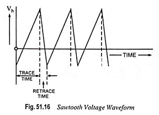
In Fig. 51.14(a) a sawtooth voltage waveform is shown, which is an ideal one. In this waveform retrace time is zero. But in practice it is not possible to achieve this, so there is some retrace time of waveform, as shown in Fig. 51.16. During this retrace time, the spot moves from right to left and leads to confusion. So this trace is blanked out by supplying a high – ve voltage to the grid during the retrace time. This blanking voltage is usually triggered by time base generator.
8. Calibration Circuit: Normally an oscillator, which generates a known and fixed voltage in square waveform, is fitted in the CRO for calibration purpose.
9. Intensity (Z-axis) Modulation: The intensity (or brightness) of the CRT trace depends upon the strength of the electron beam and the kinetic energy imparted to each electron in the beam by the accelerating electrodes. Thus, the strength of the electron beam can be comparatively easily controlled, and therefore, by this method control over intensity can be had.
The X-axis of the CRT is the horizontal channel, and the Y-axis is the vertical channel. It is common practice to refer the intensity modulation channel as the Z-axis. Many oscilloscope models contain circuitry to vary the intensity through an external jack that is usually labelled Z-axis, Z-input, or intensity modulation.
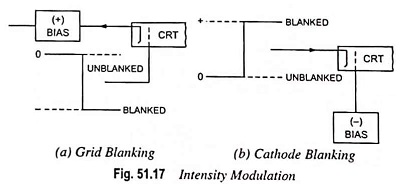
Two popular methods of accompling intensity (Z-axis) modulation are shown in Fig. 51.17. In Fig. 51.17(a), the cathode of CRT is held constant by a bias supply, and the Z-axis signal is applied to a control grid. In Fig. 51.17(b), on the other hand, there is exactly the opposite situation i.e., the control grid bias is kept constant, and the Z-axis signal is applied to the cathode.
In most oscilloscopes using a Z-axis input, it is necessary merely to reduce the intensity (using the normal front panel intensity control) so that the beam is just barely extinguished. If this is done when the Z-axis signal is zero, then application of a signal will brighten the CRT trace.
Periodic positive pulses are applied to the grid (alternatively negative pulses are applied to the cathode) to brighten the beam during its sweep period. Such periodically brightened spots may be used as markers for time calibration of the main waveform.