Instruction Set of 8085:
The Instruction Set of 8085 can be categorised into five different groups based on the nature of functions the instruction carry out:
- Data Transfer Group
- Arithmetic Group
- Logic Group
- Branch Group
- Stack, Input/Output, and Machine Control Group.
The following section explains all the instructions in each group, The notations used in the Instruction Set of 8085 are :
Notation and Meaning
- M : Memory location pointed by HL register pair
- r : 8-bit register
- rp : 16-bit register pair
- TS : Source register
- rd : Destination register
- addr : 16-bit address/8-bit address
1.Data Transfer Group:
The data transfer group instructions load the given data into register, copy data from register to register, and copy data from register to memory location and vice versa. This group consists of following set of instructions. These Instruction Set of 8085 do not affect any flag in the flag register.
- MVI r, data (8-bit)
- MVI M, data (8-bit)
- MOV rd, rs
- MOV M, rs
- MOV rd, M
- LXI rp, data (16-bit)
- STA addr
- LDA addr
- SHLD addr
- LHLD addr
- STAX rp
- LDAX rp
- XCHG
2.Arithmetic Group:
Arithmetic group instructions add, subtract, increment or decrement data in registers or in memory. In addition, there is one instruction which adjusts 8-bit data to form BCD numbers.
ADD : This group consists of following set of instructions :
- ADD r
- ADD M
- ADI data (8)
- ADC r
- ADC M
- ACI data (8)
- DAD rp
SUBTRACT : This group consists of the following set of instructions
- SUB r
- SUB M
- SUI data
- SBB r
- SBB M
- SBI data
Decimal Adjust Accumulator DAA:
This Instruction Set of 8085 adjusts accumulator to packed BCD (Binary Coded Decimal) after adding two BCD numbers.
Instruction works as follows :
- If the value of the low — order four bits (D3 – D0) in the accumulator is greater than 9 or if auxiliary carry flag is set, the instruction adds 6 (06) to the low-order four bits.
- If the value of the high-order four bits (D7 – D4) in the accumulator is greater than 9 or if carry flag is set, the instruction adds 6(60) to the high-order four bits.
3.Branch Group:
The branch group instructions allow the microprocessor to change the sequence of a program, either unconditionally or under certain test conditions. This group include :
- Jump instructions
- Call and Return instructions
- Restart instructions
JUMP : This group consists of the following set of instructions
- JMP addr
- J condition addr
- PCHL
4.Logic Group:
Logic group instructions perform logic operations such as AND, OR and XOR, compare data between registers or between register and memory, rotate and complement data in registers.
Logical Operations : This group consists of the following set of instructions.
- ANA r
- ANA M
- ANI data
- XRA r
- XRA M
- XRI data
- ORA r
- ORA M
- ORI data
- CMP r
- CMP M
- CPI data
- STC
- CMC
- CMA
5.Stack Operations, Input/Output and Machine Control Group:
Before going to study the Instruction Set of 8085 from this group it is necessary understand what a stack is ? The stack is a part of read/write memory that is used for temporary storage of binary information during the execution of a program. The binary information is basically the intermediate results and the return address in case of subroutine calls.
- For the application programs, the internal memory of the microprocessor (registers) is not sufficient to store the intermediate results. These intermediate results can be stored temporarily on the stack and can be referred back when
- A subroutine is a group of instructions, performs a particular subtask which is executed number of times. It is written separately. The microprocessor executes this subroutine by transferring program control to the subroutine program. After completion of subroutine program execution, the program control is returned back to the main program. The use of subroutines is a very important technique in designing software for microprocessor systems because it eliminates the need to write a subtasks repeatedly; thus it uses memory more efficiently. For implementation of subroutine technique, it is necessary to define stack. In the stack, the address of the Instruction Set of 8085 in the main program which follows the subroutine call is stored.
The stack is a portion of read/write memory set aside by the user for the purpose of storing information temporarily. When the information is written on the stack, the operation is called PUSH. When the information is read from stack, the operation is called a POP.
The microprocessor stores the information, much like stacking plates. Using this analogy of stacking plates it is easy to illustrate the stack operation.
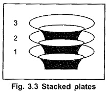
Fig. 3.3 shows the stacked plates. Here, we realize that if it is desired to take out the first stacked plate we will have to remove all plates above the first plate in the reverse order. This means that to remove first plate we will have to
Fig. 3.3 Stacked plates remove the third plate, then the second plate and finally the first plate. This means that, the first information pushed on to the stack is the last information popped off from the stack. This type of operation is known as a first in, last out (FILO). This stack is implemented with the help of special memory pointer register. The special pointer register is called the stack pointer. During PUSH and POP operation, stack pointer register gives the address of memory where the information is to be stored or to be read. The stack pointer’s contents are automatically manipulated to point to stack top. The memory location currently pointed by stack pointer is called as top of stack.
The stack pointer SP, is a 16-bit register in the 8085A which is manipulated by the microprocessor’s control section, during stack related Instruction Set of 8085.
Stack Operations :
This group consists of the following set of instructions
- LXI SP, data and SPHL
- PUSH and POP instructions
- CALL and RETURN instructions
- RESTART instructions
- XTHL
- SPHL