Tap Changing Auto Transformer:
Fig. 15.6 shows diagrammatically Tap Changing Auto Transformer. Here, a mid-tapped auto-transformer or reactor is used. One of the lines is connected to its mid-tapping. One end, say a of this transformer is connected to a series of switches across the odd tappings and the other end b is connected to switches across even tappings. A short-circuiting switch S is connected across the auto transformer and remains in the closed position under normal operation.
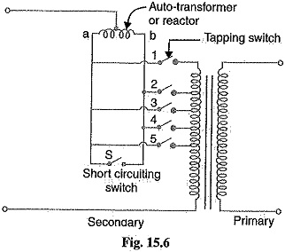
In the normal operation, there is no inductive voltage drop across the auto transformer. Referring to Fig. 15.6, it is clear that with switch 5 closed, minimum secondary turns are in the circuit and hence the output voltage will be the lowest. On the other hand, the output voltage will be maximum when switch 1 is closed.
Suppose now it is desired to alter the tapping point from position 5 to position 4 in order to raise the output voltage. For this purpose, short-circuiting switch S is opened, switch 4 is closed, then switch 5 is opened and finally short-circuiting switch is closed. In this way, tapping can be changed without interrupting the supply.
It is worthwhile to describe the electrical phenomenon occurring during the tap changing. When the short-circuiting switch is opened, the load current flows through one-half of the reactor coil so that there is a voltage drop across the reactor. When switch 4 is closed, the turns between points 4 and 5 are connected through the whole reactor winding. A circulating current flows through this local circuit but it is limited to a low value due to high reactance of the reactor.