Receiver Types:
There are Two Receiver Types namely, Pilot Carrier Receiver and a Suppressed Carrier Receiver; the suppressed carrier receiver incorporates a frequency synthesizer for extra stability and also is used to show how ISB may be demodulated.
Pilot Carrier Single Sideband Receiver:
As shown in, Figure 6-46, in block form, a pilot-carrier receiver is a fairly straightforward communications receiver with trimmings. It uses double conversion, and AFC based on the pilot carrier. AFC is needed to ensure good frequency stability, which must be at least I part of 107 (long-term) for long-distance telephone and telegraph communications. Note also the use of one local crystal oscillator, with multiplication by 9, rather than two separate oscillators; this also improves stability.
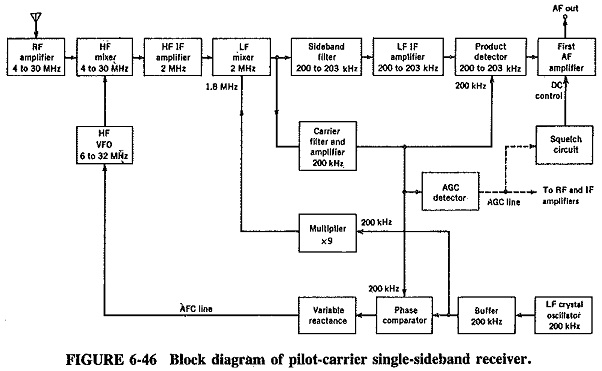
The output of the second mixer contains two components the wanted sideband and the weak carrier. They are separated by filters, the sideband going to the product detector, and the carrier to AGC and AFC circuits via an extremely narrowband filter and amplifier. The output of the carrier amplifier is fed, together with the buffered output of the crystal oscillator, to a phase comparator. This is almost identical to the phase discriminator and works in a similar fashion. The output depends on the phase difference between the two applied signals, which is zero or a positive or negative dc voltage, just as in the discriminator.
The phase difference between the two inputs to the phase-sensitive circuit can be zero only if the frequency difference is zero. Excellent frequency stability is obtainable. The output of the phase comparator actuates a varactor diode connected across the tank circuit of the VFO and pulls it into frequency as required.
Because a. pilot carrier is transmitted, automatic gain control is not much of a problem, although that part of the circuit may look complicated. The output of the carrier filter and amplifier is a carrier whose amplitude varies with the strength of the input signal, so that it may be used for AGC after rectification. Automatic gain control is also applied to the squelch circuit, as explained earlier. It should also be mentioned that Receiver Types of this type often have AGC with two different time constants. This is helpful in telegraphy reception, and in coping to a certain extent with signal-strength variations caused by fading.
Suppressed Carrier receiver:
A typical block diagram is shown in Figure 6-47. This is actually a much simplified version of the receiver of Figure 6-18, which is capable of receiving all forms of AM but has here been shown in the ISB mode. The receiver has a number of very interesting features, of which the first is the fixed-frequency RF amplifier.
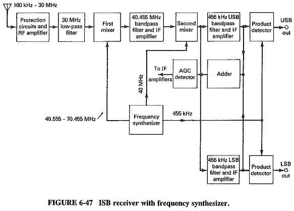
This may be wideband, covering the entire 100-kHZ to 30-MHz receiving range; or, optionally, a set of filters may be used, each covering a portion of this range. The second very interesting feature is the very high first intermediate frequency, 40.455 MHz. Such high frequencies have been made possible by the advent of VHF crystal bandpass filters. They are increasingly used by SSB receivers, for a number of reasons. One, clearly, is to provide image frequency rejections much higher than previously available. Another reason is to facilitate receiver tuning. In the RA 1792, which is typical of high-quality professional Receiver Types, a variety of tuning methods are available, such as push-button selection, or even automatic selection of a series of wanted preset channels stored in the microprocessor memory. However, an important method is the orthodox continuous tuning method, which utilizes a tuning knob. Since Receiver Types of this type are capable of remote tuning, the knob actually adjusts the voltage applied to a varactor diode across the VFO in an indirect frequency synthesizer. There is a limit to the tuning range. If the first IF is high, the resulting range (70.455 MHz ÷ 40.555 MHz = 1.74:1) can be covered in a single sweep, with a much lower first IF it cannot be tuned so easily.
It will be seen that this is, nonetheless, a double-conversion superheterodyne receiver, up to the low-frequency IF stages. After this the main differences are due to the presence of the two independent Sidebands, which are separated at this point with mechanical filters. If just a single upper and a single lower sideband are transmitted, the USB filter will have a bandpass of 455.25 to 458 kHz, and the LSB filter 452 to 454.75 kHz. Since the carrier is not transmitted, it is necessary to obtain AGC by rectifying part of the combined audio signal. From this a dc voltage proportional to the average audio level is obtained. This requires an AGC circuit time constant of sufficient length to ensure that AGC is not proportional to the instantaneous audio voltage. Because of the presence of the frequency synthesizer, the frequency stability of such a receiver can be very high. For example, one of the frequency standard options of the RA 1792 will give a long-term frequency stability of 3 parts in 109 per day.