Ramp Technique of Digital Voltmeter:
Ramp Technique – The operating principle is to measure the time that a linear ramp takes to change the input level to the ground level, or vice-versa. This time period is measured with an electronic time-interval counter and the count is displayed as a number of digits on an indicating tube or display. The operating principle and block diagram of a ramp type DVM are shown in Figs 5.1 and 5.2.
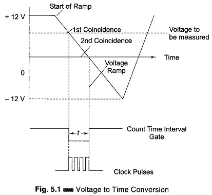
The ramp may be positive or negative; in this case a negative ramp has been selected.
At the start of the measurement a ramp voltage is initiated (counter is reset to 0 and sampled rate multivibrator gives a pulse which initiates the ramp genera-tor). The ramp voltage is continuously compared with the voltage that is being measured. At the instant these two voltage become equal, a coincidence circuit generates a pulse which opens a gate, i.e. the input comparator generates a start pulse. The ramp continues until the second comparator circuit senses that the ramp has reached zero value. The ground comparator compares the ramp with ground. When the ramp voltage equals zero or reaches ground potential, the ground comparator generates a stop pulse. The output pulse from this comparator closes the gate. The time duration of the gate opening is proportional to the input voltage value.
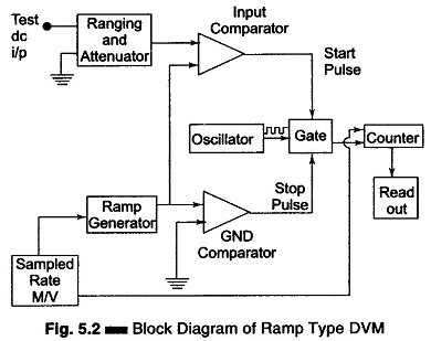
In the time interval between the start and stop pulses, the gate opens and the oscillator circuit drives the counter. The magnitude of the count indicates the magnitude of the input voltage, which is displayed by the readout. Therefore, the voltage is converted into time and the time count represents the magnitude of the voltage. The sample rate multivibrator determines the rate of cycle of measurement. A typical value is 5 measuring cycles per second, with an accuracy of ± 0.005% of the reading. The sample rate circuit provides an initiating pulse for the ramp generator to start its next ramp voltage. At the same time a reset pulse is generated, which resets the counter to the zero state.
Any DVM has a fundamental cycle sequence which involves sampling, displaying and reset sequences.
Advantages and Disadvantages:
The ramp technique circuit is easy to design and its cost is low. Also, the output pulse can be transmitted over long feeder lines. However, the single ramp requires excellent characteristics regarding linearity of the ramp and time measurement. Large errors are possible when noise is superimposed on the input signal. Input filters are usually required with this type of converter.