Electromechanical AD Converter:
Another area of application in which Electromechanical AD Converter is very important, involves the translation of the angular position of a shaft into digital information. (A very common application of this type of conversion is found in large radar installations, where the azimuth and elevation information are determined directly from the shaft position. There are many other examples in aircraft and aerospace fields.)
The method is not necessarily limited to rotational information, since rectilinear information can be translated into rotational information by means of a gearing arrangement.
In any case, the job involves changing position information (which can usually be considered as analog information, since it is continuous) into equivalent digital information. This is most generally obtained by the use of a code wheel, as shown in Fig. 17.31.
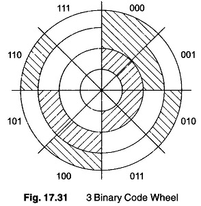
This particular wheel is coded in a straight binary fashion and represents 3 bits. The wheel is divided into three concentric bands, each representing one bit. The innermost band is divided into two equal segments and represents the MSB. The middle band is divided into four equal segments and represents the second MSB. The outer band has eight equal segments and is the LSB.
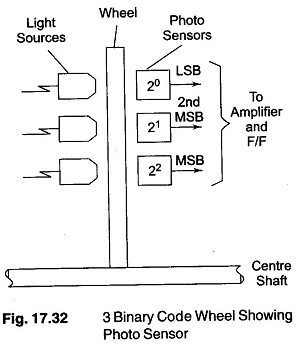
If the light areas on the wheel are transparent and the dark areas are opaque, the digital information can be obtained by placing light sources and photo sensors on opposite sides of the disk, as shown in Fig. 17.32. The output of the sensor is high if light is sensed and low if no light is sensed. These outputs then represent I s and Os and can be amplified, passed through logic circuits and used to set F/F. Such system is called an optical encoder.
The sensing could also be accomplished by placing a brush on each band making the light areas conducting and the dark areas insulating.
Now consider the wheel positioned under the sensors, such that the output reads 011. Further, let us assume that the wheel is very near the dividing line between 100 and 011. If there is an ambiguity in reading the LSB (that is, the sensor cannot decide whether to read 1 or 0, since it is right on the dividing line), the output may vary between 011 and 010. This is and not too bad, since the output is jumping only from one adjacent position to the next. However if the ambiguity is in the MSB, the results could be disastrous, since the output jumps from 011 to 111, which is a 180o
It might be quite difficult to resolve the problem of sensing when the wheel stops on the dividing line, and it may be better to use a different code.
A code which changes only one bit at a time is used when going from any one position to the next. This ensures an ambiguity in only one position and eliminates the 180° ambiguity. Such a code used is called a gray code.
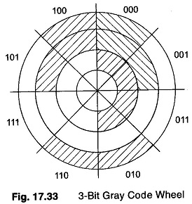
A code wheel constructed using a gray code is shown in Fig. 17.33. An examination of the wheel shows that the greatest error caused by a reading ambiguity is one segment of rotation.
The 3-bit wheel, has the ability to digitise the shaft position into an equivalent 3-bit binary number. This implies eight positions around the wheel, each shaft position
To obtain a closer reading, it is only necessary to add extra bands to the code wheel and hence extra bands to the code wheel and hence extra bits to the digit number. In general, the degree of resolution obtained is given by 3600/2n, where n is the number of bits in the binary number.