Double Stub Matching:
If a transmission-line matching device is to be useful in a range of different matching situations, it must have as many variable parameters, or degrees of freedom, as the standing-wave pattern. Since the pattern has two degrees of freedom (the SWR and the position of the first maximum), so must the Double Stub Matching.
A single stub of adjustable position and length will do the job very well at frequencies below the microwave range. (This frequency range is not rigidly defined, but it is commonly understood to occupy the spectrum from 1 to 100 GHz. It is also called broadly the centimeter range, since the two extreme frequencies correspond to wavelengths of 30 and 0.3 cm, respectively.) At such high frequencies coaxial lines are employed instead of parallel-wire lines, and difficulties with screened slots are such that stubs of adjustable position are not considered.
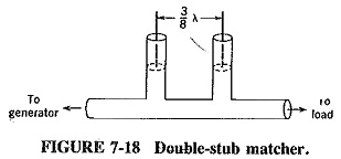
To provide the second degree of freedom, a second stub of adjustable position is added to the first one. This results in the Double Stub Matching of Figure 7-18 and is a commonly used matcher for coaxial microwave lines. The two stubs are placed 0.375 λ apart (λ corresponding to the center frequency of the required range), since that appears to be the optimum separation. Two variables are provided, and very good matching is possible. Not all loads can be matched under all conditions, since having a second variable stub is not quite as good as having a stub of adjustable position.
Such a matcher is normally connected between the load and the main transmission line to ensure the shortest possible length of mismatched line. It naturally has the same characteristic impedance as the main line, and each stub should have a range of variation somewhat in excess of half a wavelength. The method of adjustment for matching is best described as “guesstimation,” i.e., trial and error, which may or may not be preceded by a preliminary calculation.
When trial and error is used, the stub nearest to the load is set at a number of points along its range, and the farther stub is racked back and forth over its entire range (at each setting point of the first stub) until the best possible match has been achieved. The SWR is, of course, monitored constantly while adjustment is taking place. Unless the load is most unusual, for example, almost entirely reactive, it should be possible to reduce the SWR on the main line to below about 1.2 with this matcher.
If almost perfect matching under all conceivable conditions of SWR and load impedance is required, a triple-stub tuner should be used. This is similar to the Double Stub Matching tuner but consists of three stubs, adjustable in length and placed 0.125 λ apart (the optimum separation in this case)