Coal Mining Process Diagram:
The motors used for Coal Mining Process Diagram must be flame proof. They operate at high ambient temperatures. Sometimes the environment may be humid and the motors should have humid proof insulation. The motor must satisfy very stringent specifications.
The motors used in Coal Mining Process Diagram can be classified into two groups. The motors in the first group are drives for mine auxiliaries such as compressors, pumps, etc. The motors of the second group are used to drive the cutters, drillers, etc., which are directly used in the process of mining.
To determine the rating of the motor the load diagram must be known. One of the criteria discussed in Chapter 5 may be used to determine the rating.
The motors used for direct mining process must satisfy the following requirements:
- Coal cutting or drilling machines do not require any speed control.
- High starting torque may be required. High torque squirrel cage motors (double cage) find application as drives for Coal Mining Process Diagram cutting equipment.
The motor must be capable of frequent starts and stops. The hauling takes place in stages. If a clutch is used, a heavy starting torque may not be required. Constant torque and constant power operations of the motor may be required. To meet these requirements the best suited motor is a slip ring motor started with rotor resistance starter, which limits the starting current, besides giving a high starting torque.
As mine winder (motor) the following motors find application:
Ward Leonard controlled dc motor. Slip ring motor with rotor resistance control.
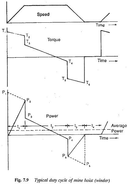
The drive speed of the mine winders must be precisely controlled. The choice of the motor rating is based on the load diagram or duty cycle of the mine winder. A typical load diagram of a mine winder is shown in Fig. 7.9. , The duty cycle is such that the mine winder starts from zero speed. It is accelerated to rated speed, which is maintained constant for a period of time. The motor is braked to decelerate the load to zero speed. The next cycle starts after a rest period. The drive motor should have sufficient starting torque to start the winder on load. This torque has a constant component and accelerating, torque. Some regeneration is possible during braking. The torque due to the rope weight must be balanced. The torque/time diagram in Fig. 7.9 is simplified and does not consider this. The power diagram can be determined, using which the rating of the motor can be determined, based on the methods described in Chapter 5. While deriving this power diagram, speed changes must be taken into consideration. The typical power curve shown in Fig:7.9 assumes constant speed and hence it is made up of striaght lines. Based on this also, a slip ring motor with rotor resistance starter is best suited.
The centrifugal pumps are used in mines for several jobs. The drive motors used for these pumps have been discussed in detail. For fan drives normal squirrel cage motors may be used.