Types of DC Motor:
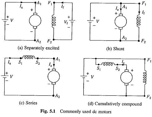
The commonly used Types of DC Motor are shown in Fig. 5.1. In a separately excited motor, the field and armature voltages can be controlled independent of each other. In a shunt motor, field and armature are connected to a common source. In case of a series motor, field current is same as armature current, and therefore, field flux is a function of armature current. In a cumulatively compound motor, the magneto-motive force of the series field is a function of armature current and is in the same direction as mmf of the shunt field.
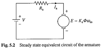
The steady state equivalent circuit of armature of a dc machine is shown in Fig. 5.2. Resistance Ra is the resistance of the armature circuit. For separately excited and shunt motors, it is equal to the resistance of armature winding and for series and compound motors it is the sum of armature and field winding resistances. Basic equations applicable to all Types of DC Motor are
where
Φ – is the flux per pole, Webers;
Ia – the armature current, A;
V – the armature voltage V;
Ra – the resistance of the armature circuit, ohms;
ωm – the speed of armature, rad/sec;
T – the torque developed by the motor, N-m; and
Ke – the motor constant.
From Eq. (5.1) to (5.3)
Shunt and Separately Excited Motors:
In case of shunt and separately excited motors, with a constant field current, the flux can be assumed to be constant. Let
![]()
Then from Eqs. (5.1), (5.3) and (5.4) to (5.6)
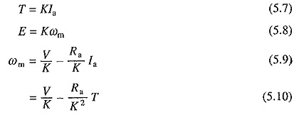
The speed-torque and torque-current characteristics of a separately excited motor for rated terminal voltage and full field are shown in Fig. 5.3. The speed-torque curve is a straight line. The no load speed ωm0 is determined by the values of armature voltage and field excitation. Speed decreases as torque increases and speed regulation depends on the armature circuit resistance (Eq. (5.10)). The usual drop in speed from no load to full load, in case of a medium size motor,
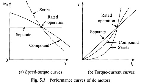
is of the order of 5%. Separately excited motors are employed in applications requiring good speed regulation and adjustable speed.
Series Motor:
In series motors, the flux is a function of armature current. In unsaturated region of magnetization characteristic, Φ can be assumed to be proportional to Ia. Thus,
![]()
Substituting in Eqs. (5.3), (5.4) and (5.5) gives
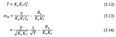
where armature circuit resistance Ra is now the sum of armature and field winding resistances. The speed-torque and torque-current characteristics of a series motor at rated terminal voltage and full field are shown in Fig. 5.3. Series motors are suitable for applications requiring high starting torque and heavy torque overloads. Since torque is proportional to the armature current squared, for the same increase in torque, increase in motor current is less compared to that in a separately excited motor where torque is proportional to armature current. Thus, during heavy torque overloads and starting, power overload on the source and thermal overloading of the motor are kept limited to reasonable values. According to Eq. (5.14), as speed varies inversely as the square root of torque, machine runs at a large speed at light load. Generally, mechanical strength of a Types of DC Motor permit it to operate upto about twice rated speed. Hence, the series motor should not be used in those drives where there is a possibility of the load torque being dropped to the extent that the speed may exceed twice rated value.
Compound Motor:
Speed-torque and torque-current characteristics of a cumulative compound motor are also shown in Fig. 5.3. The no load speed depends on the strength of shunt field and slope of the characteristic on the strength of series field. Cumulative compound motors are used in those applications where a drooping characteristic similar to that of a series motor is required and at the same time the no load speed must be limited to a safe value; typical examples are lifts and winches. It is also used in intermittent load applications, where the load varies from almost no load to very heavy loads. In these applications a fly-wheel may be mounted on the motor shaft for load equalisation. This apart from equalising load on the supply, permits the use of a smaller size motor. Pressing machine is a typical example of this type of application.
The characteristics of Fig. 5.3, which are obtained at rated terminal voltage and full field are known as natural speed-torque characteristics. Rated (or full load) speed is known as the base speed.
Universal Motor:
The universal motor can run both on dc and ac supply. It is essentially a dc series motor, with some differences in construction; which are mainly introduced to get satisfactory performance on ac. In series motor, torque depends on the product of armature current and field flux. Reversal of the terminal voltage reverses both the armature current and field flux. Consequently, torque remains in the same direction. Therefore, when fed from an ac source, the series motor produces unidirectional torque. Although the torque fluctuates at a frequency of 100 Hz between zero and its peak value, its fluctuations are smoothened out by motor inertia and the motor runs at a uniform speed.
A simple dc series motor does not operate well on ac. Hysteresis and eddy current losses that occur in field poles and yoke reduce motor efficiency and increase thermal loading. The alternating flux produces large induced currents in the coils that are short circuited by brushes during commutation. This causes excessive sparking at the commutator. Motor power factor is very poor due to large inductance of field and armature. Universal motor is specially constructed to solve these limitations. In addition to the armature, field poles and yokes are also laminated to reduce eddy current losses. High permeability silicon steel lamination are used to reduce hysteresis loss. A compensating winding is used in series with the armature to reduce armature inductance. The field inductance is lowered by using fewer turns and shallow pole pieces. In spite of these changes, when fed from ac, commutation is worse than when fed from dc. Therefore, their power ratings are seldom higher than 1 kW. No load speed is high, but generally not high enough to damage the motor.
Most universal motors are manufactured for use at speeds in excess of 3000 rpm. This is the maximum speed of an induction motor when fed from a 50 Hz supply. Below this speed induction motor is generally preferred. Many universal motors operate at speeds upto 12,000 rpm and can go upto 20,000 rpm. Because of high operating speeds, universal motor is much smaller in size compared to an induction or a low speed dc motor of identical rating. Because of brushes and commutator, it requires frequent maintenance and has a relatively short operating life.
Until recently, universal motor was the cheapest motor capable of running at high speeds and having relatively very small weight and size. The brushless Types of DC Motor or a single phase induction motor fed from variable frequency inverter may become its competitor in near future.
Some applications of universal motor are fans, electric drills, home appliances etc.
Permanent Magnet Motors:
In permanent magnet dc motors, field excitation is obtained by suitably mounting permanent magnets on the stator. Ferrites or rare earth (cobalt samarium) magnets are employed. Ferrites are commonly used because of lower cost, but the machine becomes bulky due to low retentivity. Rare earths because of their high retentivity allow a large reduction in weight and size, but they are very expensive. The permanent magnet motors are mainly employed in fractional horsepower range, but they are available upto 5 kW rating.
Use of permanent magnets for excitation eliminates field copper loss and need for field supply. Compared to the field wound motors, they are more efficient, reliable, sturdy and compact. The field flux remains constant for all loads giving a more linear speed torque characteristic. In a separately excited motor, failure of field supply can lead to runaway condition. This does not happen in permanent magnet motors. As the flux is constant in these motors, speed cannot be controlled above base speed. Such motors have applications in electric vehicles like mopeds, forklift trucks, wheel chairs etc.
DC Servo Motors:
There is no sharp dividing line between servo and conventional field wound and permanent magnet dc motors. Servo motors are intended to be used in closed loop speed and positional control systems where performance requirements are such that they cannot be achieved by a normal dc motor. A normal Types of DC Motor is designed to achieve good full load performance with minimum cost. It fails to provide good dynamic response and steady state accuracy when employed in a closed-loop drive. The servo motor on the other hand is designed to achieve good dynamic performance and steady state accuracy. It is designed to achieve the same performance in both directions of rotation, high torque to inertia ratio, low friction and smooth ripple free torque. In a Types of DC Motor, the armature inertia is proportional to length and diameter squared. In some servo motors, inertia is reduced by reducing diameter and increasing length for the same rating. In low power servo drives, where current control is not incorporated, the current during transient operation can be even higher than ten times the rated current. Commutator is designed to obtain spark-free commutation even at such large currents, which will not be possible in a common dc motor. Because of these exacting requirements servo motors are much more expensive than common dc motors. Their ratings can be from few watts (in instrument servos) to megha watts (steel rolling mills). Small servo motors are usually permanent magnet type.
Moving Coil Motors:
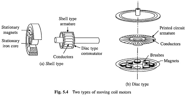
Some applications require acceleration much higher than what can be achieved in a conventional dc servo motor. Armatures of moving coil dc motors have special constructions which allow a substantial reduction in armature inertia and inductance, permitting very high accelerations. Two types of moving coil motors are shell and disc type.
Shell Type:
In order to maximize acceleration, armature inertia must be minimized. In a conventional dc motor, the armature consists of a winding housed in slots provided on a cyclinder of magnetic material, which is provided mainly to give low reluctance path for the stator field, and rotates with armature winding. Consequently, armature has high inertia. In a shell type moving coil motor (Fig. 5.4(a)), the rotor consists of only armature winding. Hence it has very low inertia. Low reluctance path for the stator field is provided by a stationary magnetic material cylinder. Armature winding consists of conductors assembled to form a thin walled cylinder. The commutator may have a cylindrical construction as in conventional dc motors or disc type construction.
Tiny motors (with diameters around 1 cm), known as micromotors, have armature winding consisting of simply varnished wires arranged in cylindrical form and a disc type commutator. Such motors are widely used in cameras, card readers, video systems etc. In bigger size motors, the armature winding is made by bonding conductors together using polymer resins and fiberglass to provide adequate mechanical strength.
Disc or Pancake Type:
The construction details are shown in Fig. 5.4(b). Armature is made in disc or pancake form, and armature conductors resemble spokes on a wheel. Armature winding is formed by stamping conductors from a sheet of copper, welding them together and placing them on a light weight disc. Conductor segments are then joined with a commutator at the centre of the disc. Note that the direction of flux is axial and armature current is radial. This is just opposite to shell type (or conventional) motors where the current is axial and flux is radial. The principle of operation is same as that of a conventional dc motor.
Disc type moving coil motors are more robust and available in sized upto few kilowatts. They find applications where axial space is at a premium such as machine tools, disc drives etc.
Moving coil motors can be provided with large number of conductors (few hundred). Therefore, torque remains almost constant as the rotor turns. This allows them to produce very smooth rotation at low speeds. The absence of iron in armature of disc type motor eliminates the associated core losses, making it more efficient than conventional dc motors. As already stated, low inertia and low armature inductance gives moving coil motors an excellent dynamic response.
Torque Motors:
DC motors designed to run for long periods in a stalled or a low speed condition are known as torque motors. A normal Types of DC Motor is designed to optimize full speed performance. In small ratings, the stalled or low speed current in normal dc motors can be 5-10 times the rated current. If these motors are allowed to run at low speed (or standstill), armature winding will get burnt by overheating and the commutator will get damaged due to heavy sparking. In case of torque motors, because of special design, the stalled and low speed current remains below safe value. Some torque motors are designed to operate at low speeds intermittently.
Applications of torque motors can be divided into three categories:
- Where the motor is required to operate in stalled condition. Here, purpose of the motor is to develop required tension or pressure on a material, similar to spring. Machine tools, spooling come under this category.
- In second category torque motor is required to move through only a few revolutions or degrees of revolution. Opening of valves, switches and clamping devices are some examples.
- This category of application involves continuous movement of the motor at low speed, e.g. reel drive.